6
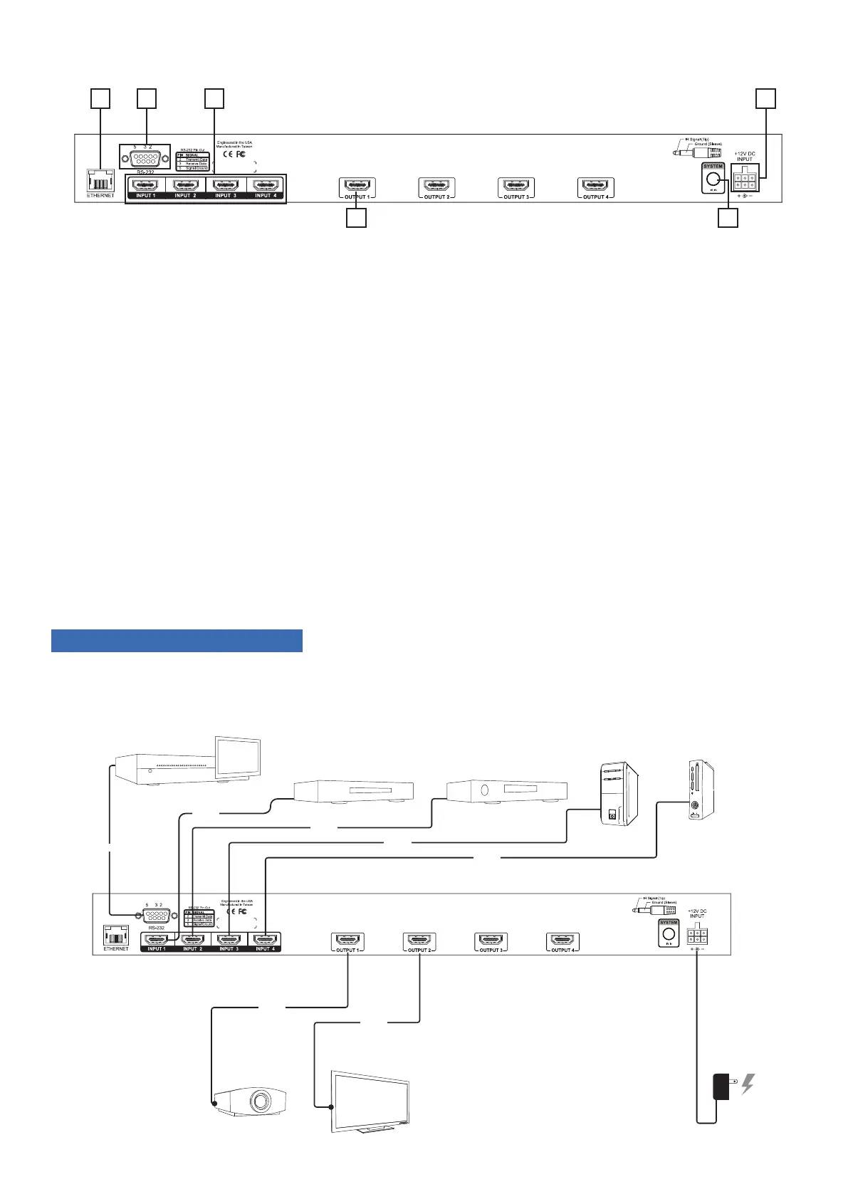
5.2. Rear Panel of the B-120-HDMATRIX-4x4 Switcher
FIGURE 2: B-120-HDMATRIX-4x4 Switcher Layout (Rear View)
A. Ethernet Port
RJ45 port for connecting an ethernet Cat5e/6 cable for IP control of the B-120-HDMATRIX-4x4
B. RS-232 control port (DB9)
To communicate with control system or Windows PC for serial control of matrix
C. HDMI Inputs (1 through 4)
Connect HDMI cables from sources to the matrix switcher for distribution
D. HDMI Outputs - 1 through 4
Connect HDMI cables from matrix switcher to displays.
E. System IR In
To connect a control system with 3.5mm mono IR input for matrix control
F. Power Jack
+12V DC, 5A power supply connection
6. INSTALLATION & SETUP
6.1. Basic Installation Diagram
Complete the basic installation section to set up the matrix switcher for media distribution before completing any other
setup. Use this diagram for reference during basic installation of the matrix switcher, sources, displays, and wiring.
FIGURE 3: B-120-HDMATRIX-4x4 Installation
Control System
AC Power
Projector
TV
Blu-ray Player
Cable/Sat Box
PC
Game Console
HDMI
HDMI
HDMI
HDMI
HDMI
HDMI
RS-232
A
CB F
D E