9
6.7.1. RS-232 Control
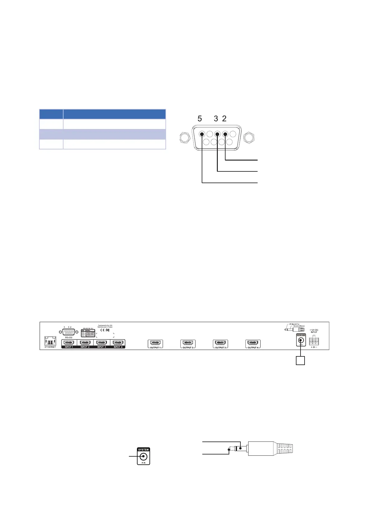
To control the B-120-HDMATRIX-4x4 with RS-232, the devices must connect using the correct pin conguration
for the control system in use.
The matrix switcher receives control data on pin 2 (RxD – Data Receive) and transmits control data on pin 3
(TxD-Data Transmit). See the diagram below for details.
Conguration for control system serial ports can vary. Refer to the documentation for the system in use to ensure
proper connection and conguration.
Note: This port is also used to communicate with a PC when using the PC Conguration Utility. Refer to the
Conguration Utility Manual for details.
Pin Function
2 RxD (Data Receive)
3 TxD (Data Transmit)
5 Ground/Common
FIGURE 4: RS-232 (DB9) Pin Congurations
6.7.2. Ethernet/IP Control
The B-120-HDMATRIX-4x4 includes an Ethernet port that can be used to control the device using Telnet Protocol.
This port follows TIA 568B standards; please refer to these standards when terminating cables.
To congure the matrix switcher for use with the driver, it will be necessary to connect the unit to a PC and access
it with the Matrix Conguration Utility. See the Conguration Utility Manual and the IP driver documentation for
complete setup instructions.
6.8. Matrix Switcher IR Connections
The ports indicated in the diagram are described below.
FIGURE 5: IR Connections
A. System IR In (3.5mm mono)
IR input port for matrix switcher IR control.
6.8.1. Matrix Switcher IR Port Conguration
The System IR In on the B-120-HDMATRIX-4x4 is 3.5mm mono and only uses this pinout conguration.
Matrix IR
Control Input
IR Signal (Tip)
GND (Sleeve)
FIGURE 6: IR Port Conguration
Consult with the manufacturer of any attached IR equipment to conrm their pinout matches before use. Visit our
website for HEX codes under the support tab of this product’s page.
DB9 Female Connector
RxD (Data Receiver
TxD (Data Transmit)
GND
A
B-120-HDMATRIX-4x4