BF (E1) 05/2016 page 16/58
4.2 Connection to a suction plant (optional)
When directly connecting a suction plant the spatial temperature exactitude, the heating-up and the
recovering times and the maximum temperature will be negatively influenced. So no suction plant should
be directly connected to the exhaust duct.
Active suction from the chamber must only be effected together with extraneous air. Perforate
the connecting piece to the suction device or place an exhaust funnel at some distance to the
exhaust duct.
CAUTION
The exhaust duct will become hot during operation.
Danger of burning.
∅ Do NOT touch the exhaust duct during operation.
5. Start up
5.1 Turning on the chamber
Warming chambers may release odors in the first few days after commissioning. This is not a
quality defect. To reduce odors quickly we recommend heating up the chamber to its nominal
temperature for one day and in a well-ventilated location.
1. Insert the plug into an appropriate socket (chap. 4.1).
The green “Standby“ LED illuminates.
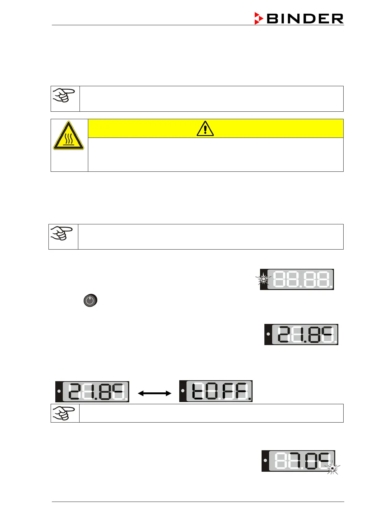
2. Press
until the display lights up.
The controller is now in normal display (actual value display).
If the chamber is operating (time functions “Continuous operation”, or
“Timer operation” with the set time just running down chap. 6.3
actual temperature value (example: 21.8 °C) is displayed
If the controller is in time function “Timer operation” with no time programmed or the set time run-off
(chap. 6.3), the chamber is inactive (no heating). The display alternately shows the actual temperature
value (example: 21.8 °C) and “tOff”:
Adjust the temperature safety device following any changes of the set-point (chap. 7).
5.2 Heating operation display
The heating is active as soon as the red heating control light in the
bottom right corner of the display slowly begins to flash depending on the
heat requirement (example: 70 °C):