EasyManua.ls Logo

Binder M Series - Page 31

Default Icon
71 pages
Print Icon
To Next Page IconTo Next Page
To Previous Page IconTo Previous Page
Loading...
M (E2) 04/2019 page 31/71
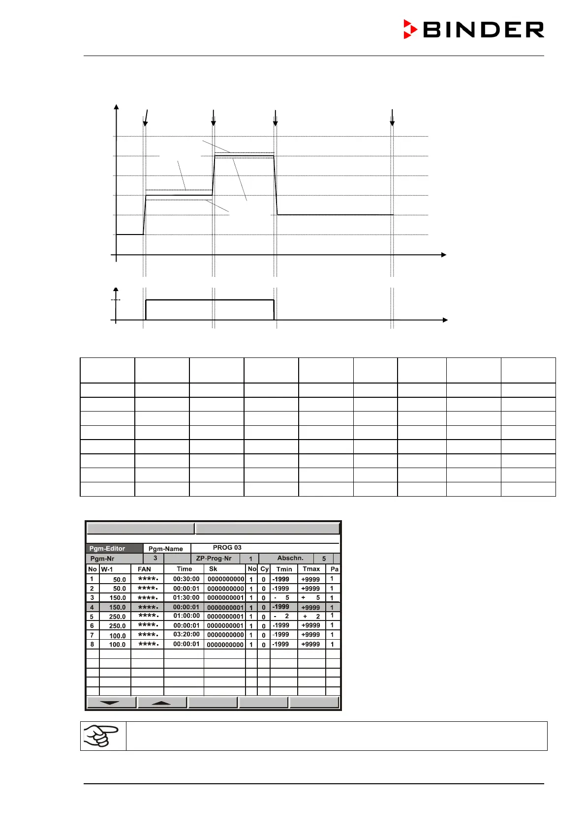
Program entry as set-point step (example)
W/°C
t/min.
01 02 03 04 05 06 07
08
0
50
100
150
200
25
0
30
120
180
380
Tolerance
minimum
Tolerance
maximum
On
Off
t/min.
Operation line 1 = air flap
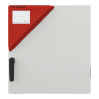
Program table corresponding to the diagram above:
Program
section
Set-point
temp.
Fan
Section
time
Operation
line1
Target
section
No. of
cycles
Min.
tolerance
Max.
tolerance
01
50
100 %
00:30:00
Off
1
0
-1999
+9999
02
50
100 %
00:00:01
Off
1
0
-1999
+9999
03
150
100 %
01:30:00
On
1
0
-5
+5
04
150
100 %
00:00:01
On
1
0
-1999
+9999
05
250
100 %
01:00:00
On
1
0
-2
+2
06
250
100 %
00:00:01
On
1
0
-1999
+9999
07
100
100 %
03:20:00
Off
1
0
-1999
+9999
08
100
100 %
00:00:01
Off
1
0
-1999
+9999
Now enter the values of the above program table into one of the 25 program places of the controller MB1:
For rapid transition phases, do NOT program any tolerance limits in order to allow maximum
heating speed.
PGM
09:17:15 15.12.13

Table of Contents

Related product manuals