Picture 8
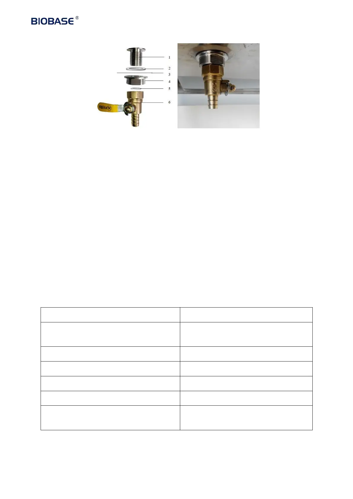
1. Drain valve connecter
2. Shim (Inner diameter*outer diameter*thicknessΦ20*Φ28*2mm)
3. Safety cabinet bottom installation holes
4. Ball coupling fastening nut
5. Rubber gasket (Inner diameter*outer diameter*thicknessΦ13*Φ19*2mm)
6. Drain valve
Take out drain valve coupling, shim(Inner diameter*outer diameter*thicknessΦ20*Φ28*2mm), Ball
nut, Rubber gaske(Inner diameter*outer diameter*thicknessΦ13*Φ19*2mm)t, Drain valve,
assembling from up to down as Picture 8 illustrated.
Don’t place equipment where dificult to operate and diconnect device.
1.5 Checking after installation
Inflow 0.53±0.025m/s , downflow
0.33±0.025m/s
Lamp lights after pressing button
Lamp lights after pressing button
Press the socket key, multimeter testing
output supply voltage