Theory of Operation
4
Elements, Analog Circuitry, and A/D Converter
These components are controlled by the computer. The Plug-in Elements in the
line section provide low level positive voltages related to the instantaneous
value of power (see
Figure 3
). The first group of solid state switches selects the
forward element, the reflected element, or ground as the input to the
preamplifier which boosts these signals to 0.1 to 2.0 volt range. The remaining
switches shown as two groups direct the output of the preamp to the analog-to-
digital converter either directly or through a peak or negative peak detector.
The analog-to-digital converter converts the voltage to a 15 digit binary
number.
Each reading output by the display is derived from up to three voltage readings
using the circuitry described above. Once these voltages are measured, all
remaining operations are performed within the computer chip as follows:
The voltages are corrected for error due to DC drift in the analog circuitry. Each
voltage is converted to square root of power using stored data tables. These
values are then combined mathematically to arrive at the final result in binary.
This is used to update the registers containing the last value, the maximum value,
or the minimum value as required. Finally, the result is converted to a decimal
number and placed into a register from which the display driving routine
operates.
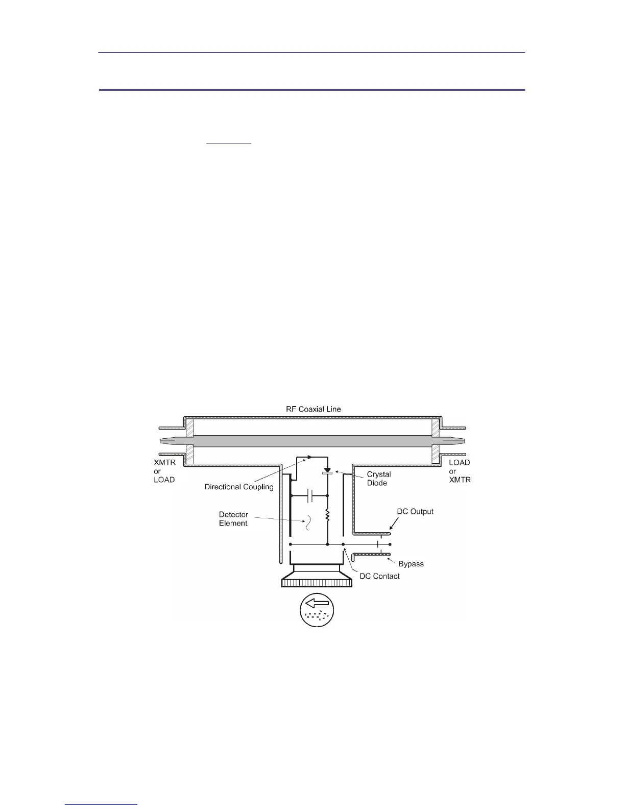
Figure 3 Plug-In Element Schematic Diagram
The coupling circuit that samples the traveling waves is in the Plug-in Element.
The circuitry of the element and its relationship to the other components of the
Thruline Watt-meter are illustrated in the schematic diagram. Energy will be
produced in the coupling circuit of the element by both mutual inductance and
capacitance from the traveling RF waves of the line section. The inductive
currents will flow according to the direction of the traveling waves producing
them. The capacitive portion of these currents is independent of the direction
of the traveling waves. Therefore, assuming that the Plug-in Element remains