Maintenance
22
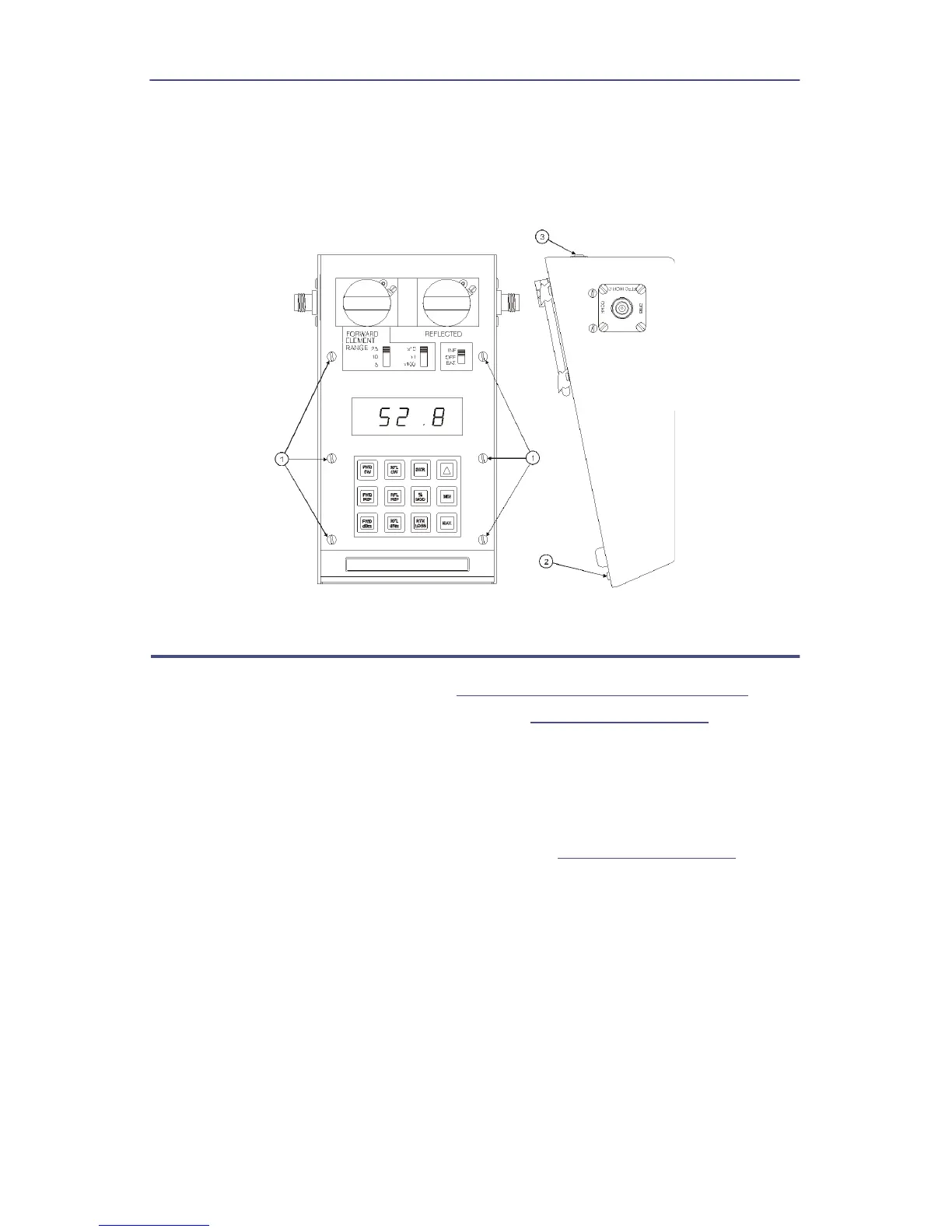
5. Lift the front panel from the housing.
Note: Be careful to clear the line section blocks.
6. Remove pads from the three toggle switches.
Figure 18 Removing Front Panel
Main Printed Circuit (PC) Board Removal
1. Remove the front panel. Refer to
"Front Panel Removal" on page 21
.
2. Disconnect cable assembly at header (J4) (
Figure 19 on page 23
, item 1).
3. Remove the six screws and washers that secure the circuit board supports
to the housing (item 2).
4. Lift the Main PC board.
Note: Locate the cable coming from the power supply assembly.
5. Disconnect the cable assembly at header (J1). (
Figure 19 on page 23
, item
3).