Multi-Purpose Thruline Wattmeter RF Power Analyst
23
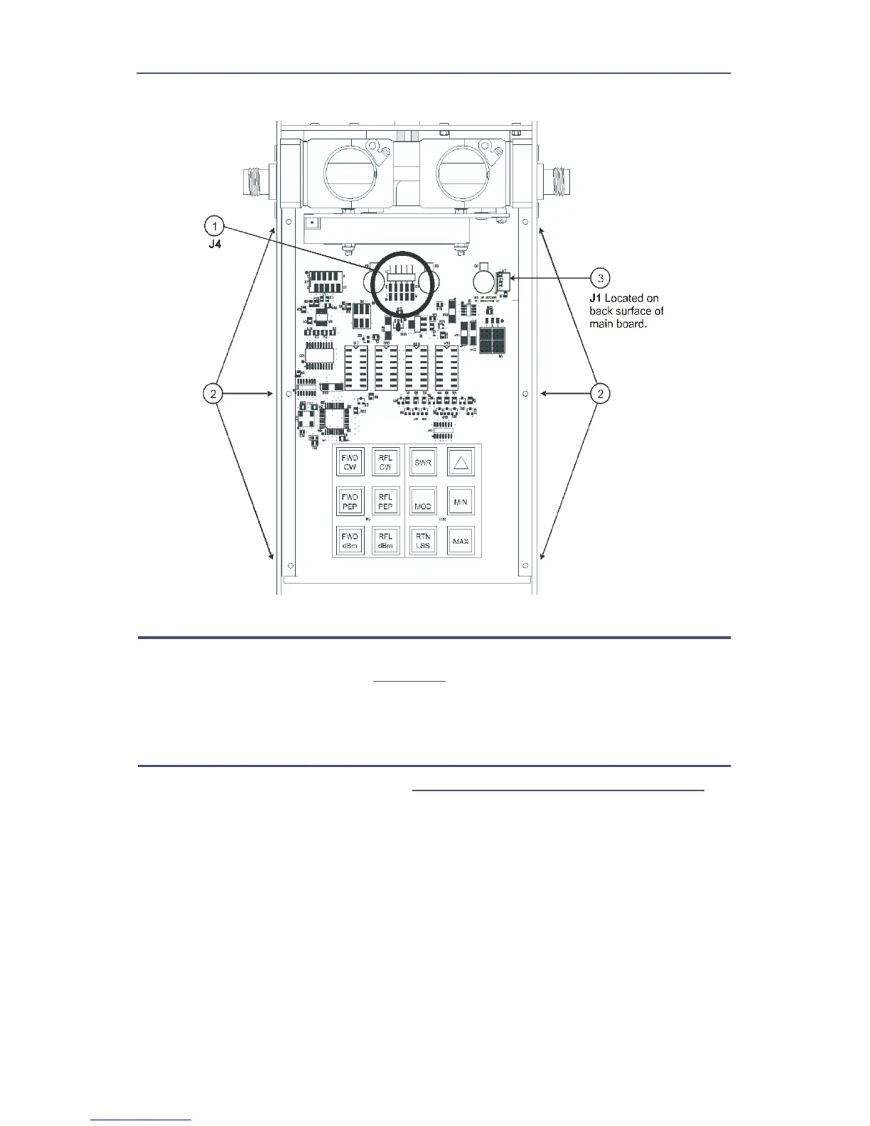
Figure 19 Removing Main PCB
QC Connectors Removal
1. Remove the eight screws (four on each connector) that secure the
connectors to the housing (
Figure 20
, item 1).
2. Remove the two “QC” connectors (item 2) by pulling them away from the
line section assembly.
Line Section Removal
1. Remove the QC connectors (See
"QC Connectors Removal" on page 23
).
2. Remove the four screws and lock washers that secure line section assembly
to the housing (item 3).
3. Spread apart the sides of the lower housing assembly far enough to allow
the line section assembly to be removed.
Note: Use minimum pressure when performing this step.