Maintenance
24
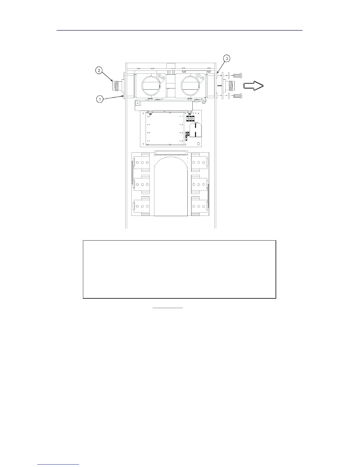
Figure 20 Removing QC Connectors and Line Section
4. Remove the two hex nuts (
Figure 21
, item 5) that secure the PCB.
5. Remove the cover (item 6) and spacers (item 7).
6. Disconnect the ribbon cable assembly from the PC board header (P1).
7. Remove the two screws (item 4) that secure the PCB to the line section then
pull the PC board assembly (item 3) away from the line section subassembly.
8. Remove the spacers (item 2).
9. Remove keying beads (item 1) from the element wiper contacts on the PC
board assembly.
CAUTION
This instrument contains static sensitive electronic
components. Before opening or servicing the unit, make sure
that you understand and practice electrostatic discharge
component handling. Failure to comply may result in
permanent damage to sensitive components.