Multi-Purpose Thruline Wattmeter RF Power Analyst
9
The Model 4391A arrives at values of CW power by a method quite different from
analog meters such as the Model 43, also manufactured by Bird Electronic. While
the two instruments will agree when the measured wave is of constant
amplitude, AM or SSB waves will result in different indications (in the CW mode).
This is because the analog instrument uses the inertia of the microammeter to
“time-average” the varying signal coming from the element, whereas the Model
4391A uses peak and negative peak detector circuits to measure peak and
minimum square root of power and combines them using the equation:
With this technique, operation of CW mode is predictable regardless of
envelope shape (see
Figure 4
).
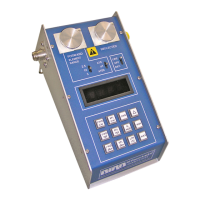
Reading Reflected CW Power
Operation of the reflected CW power mode is identical to that for forward CW
power described above with two exceptions: the readings are taken from the
element in the socket marked “REFLECTED” and the range of the element is
assumed to be 1/10 the range indicated by the range switches.
Figure 7 Reflected Power (CW)
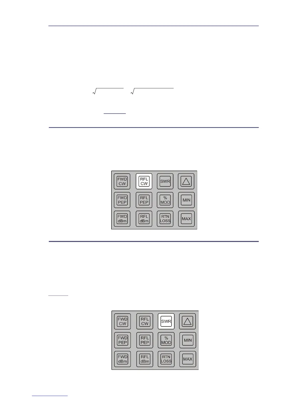
Reading SWR
Two elements with a 10 to 1 power range ratio are required for this mode. Press
the SWR key momentarily. If average forward power is between 10% and 120% of
the scale and the average reflected power is less than 120% of the reflected
element range, SWR will be displayed. If any of the above conditions are not met,
an error message will be displayed. Two arrows pointing to the right — or
“greater-than” symbols — indicate over-range, while two left-pointing arrows —
or “less-than” symbols — indicate under-range or too little power. Refer to
Table 2
.
Figure 8 Standing Wave Ratio (SWR)
CW POWER
Peak Power Minimum Power+
2
------------------------------------------------------------------------------------
2
=