Multi-Purpose Thruline Wattmeter RF Power Analyst
11
Measuring Amplitude Modulation
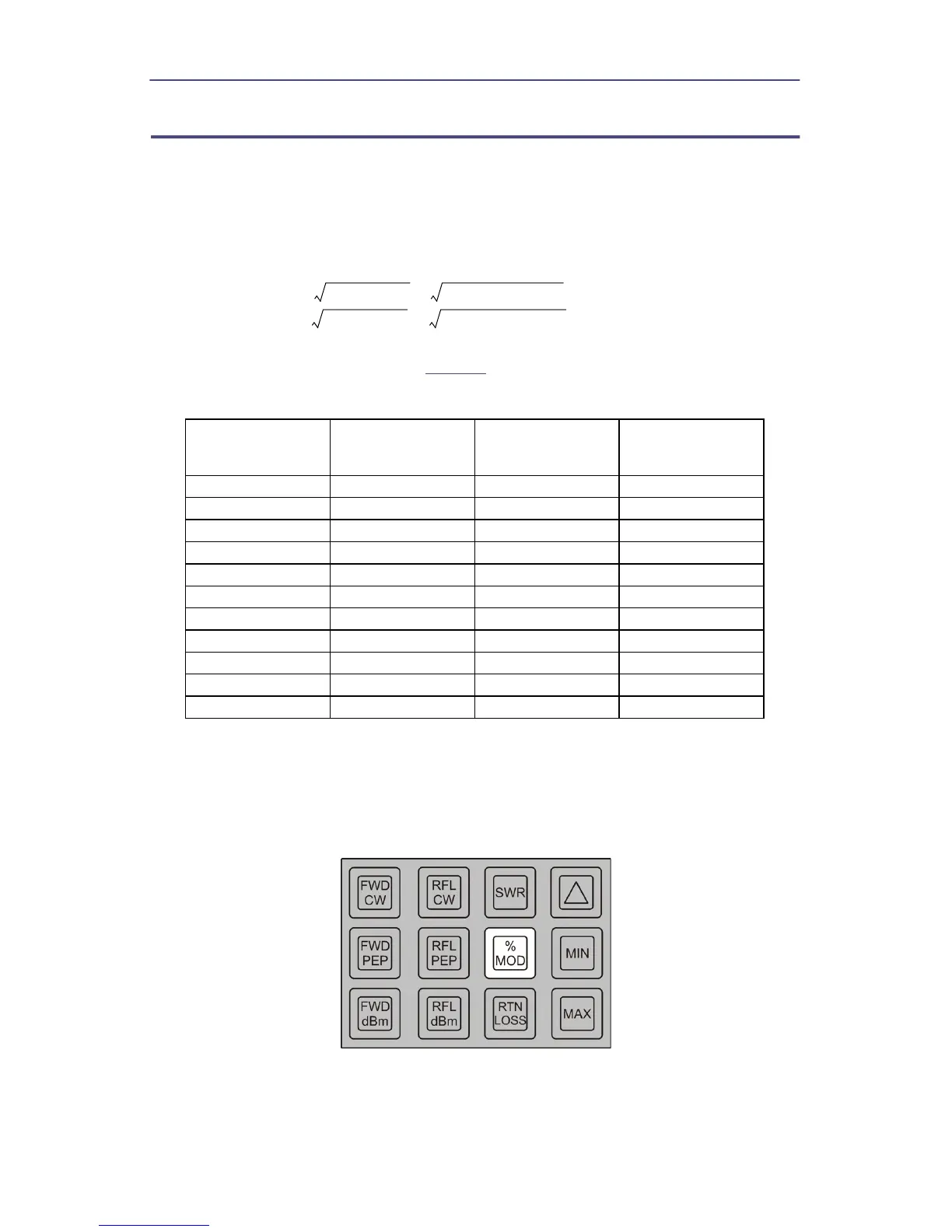
Only a forward element is required for this mode. Point the element in the
direction of forward power and press % MOD. Modulation is displayed directly
in percent, provided the average signal is above 10% and the PEP of the signal is
below 400% of the element’s nominal full scale. For specified accuracy, the
average CW power levels must be greater than one-third of full scale.
Modulation is calculated as follows:
and is therefore limited to the range of 0 to 99.9 percent. Over-modulation will be
indicated as 99.9 percent. Refer to
Table 3
.
Table 3 - Amplitude Modulation
Because of the threshold of the RF diode, a modulated signal which has a
minimum power level below 0.3 percent of full scale will result in high
modulation reading with uncertain accuracy.
Figure 10 Amplitude Modulation (%)
Peak /
CW Power
% Modulation
Peak /
CW Power
% Modulation
1.00 0 2.40 55
1.10 5 2.56 60
1.21 10 2.72 65
1.32 15 2.89 70
1.44 20 3.06 75
1.56 25 3.24 80
1.69 30 3.42 85
1.82 35 3.61 90
1.96 40 3.80 95
2.10 45 4.00 100
2.25 50
MODULATION
Peak Power Minimum Power–
Peak Power Minumum Power+
------------------------------------------------------------------------------------- 1 0 0=