Maintenance
18
Initial Setup
Note: On a clean flat workspace perform the following setup pro-
cedure:
1. Remove the front panel. Refer to
"Front Panel Removal" on page 21
.
2. Insert a DC feed-in adapter into the FWD element of the socket.
3. Insert a metal dust plug (supplied with the instrument) into the RFL
element socket.
4. Connect a BNC to BNC cable assembly from the output of calibrator/source
to the DC feed-in adapter.
5. Set the RF Power Analyst range switches to the 10 and x100 positions.
6. Connect AC power and place the LINE/OFF/BATT switch to the LINE setting.
7. Switch on the Calibrator/Source.
8. Allow it to warm up for at least one hour.
9. Set the Calibrator/Source to output 30 ±0.05 microamps.
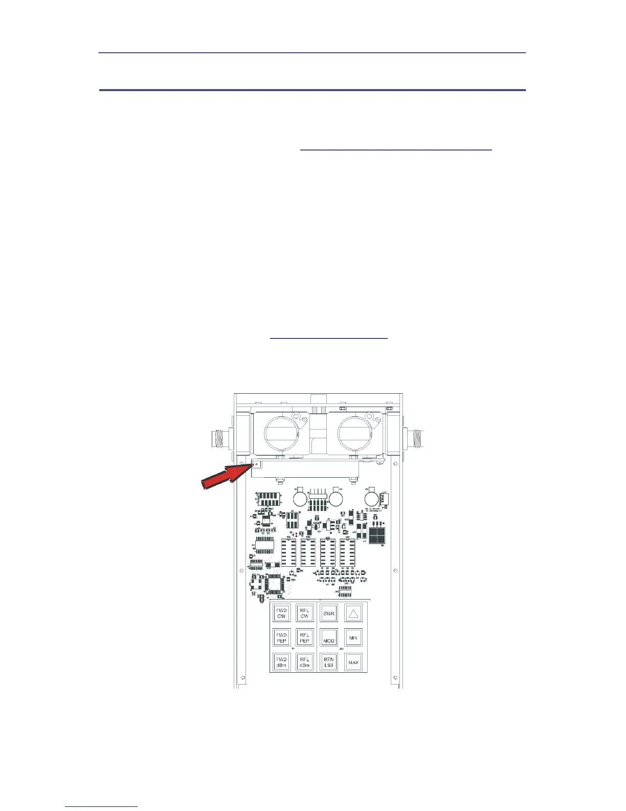
10. Adjust potentiometer, R25 (
Figure 15 on page 18
), until the RF Power
Analyst Displays 1000 ±5.
Figure 15 Calibration Potentiometer