26
Byte 3 of present output voltage
11
byte To set the low byte of current value
To set the high byte of current value
13
byte Byte 0 of the maximum voltage value
Byte 1 of the maximum voltage value
Byte 2 of the maximum voltage value
Byte 3 of the maximum voltage value
Byte 0 of output voltage value
Byte 1 of output voltage value
Byte 2 of output voltage value
Byte 3 of output voltage value
8. Entering the calibration mode(0x27)
Calibration protection state
5
byte Calibration password(0x28)
Calibration password(0x01)
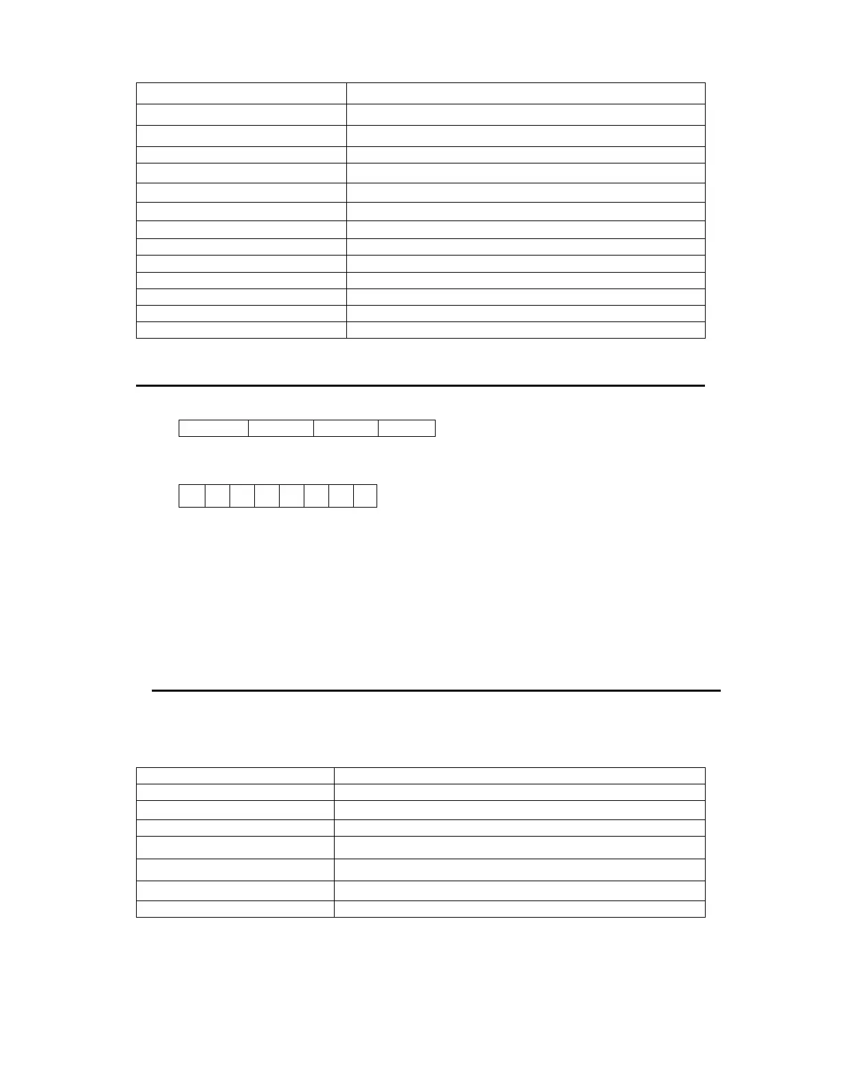
1. We use 4 bytes to represent the maximum voltage value as follows:
2. We use 1 byte to represent power supply’s state. Each bit is defined as
follows:
From higher bit to lower bit
0 bit
The output state, 0 is OFF, 1 is ON.
1 bit
Over heat protection, 0 is normal, 1 is abnormal.
2
3 bit: The output mode, 1 is CV mode, 2 is CC mode,3 is Unreg mode.
4
5
6 bit
The fan speed, 0 is stop, 5 is the maximum fan speed.
7 bit
Operation state, 0 is front panel operation mode, 1 is remote control
mode.
3. The frame format is the same as above