controlled in one of two ways. The simpler
implementation, as shown in Fig. 2, is a
SWEEP WIDTH pot in series with the ramp
output. This method of adjustment usually
requires the use of an oscilloscope, monitor-
ing either the actual output frequency or the
output of the current summing amp, at the
GCV jack.
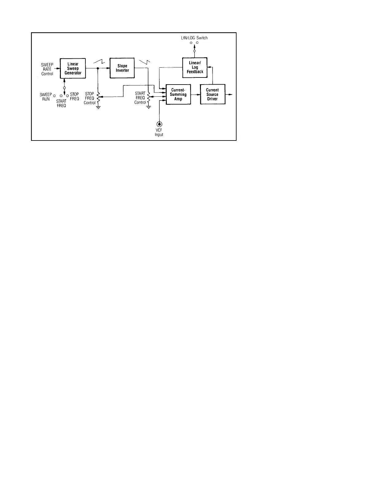
A more elaborate sweep system is pre-
sented in Fig. 5. In this system, the output of
the ramp generator is passed through an
inverter, producing a ramp with the same
endpoints but with inverted slope.
A d d i t i o n a l l y, the ramp generator can be
switched off and held at each of the two end-
points indefinitely. In both cases, because of
the inverter, one of the two pots, START
FREQ or STOP FREQ, has maximum volt-
age at its top, while the other has zero. This
enables each of the frequency limits to be set
without the sweep running. When the sweep
circuit is restarted, the summation of the two
opposite ramps forms a single ramp which
runs from the START FREQ setting to the
STOP FREQ setting, regardless of direction.
Feedback from the current source driver is
used to produce a linear or log sweep. This
system has the advantages of more accurate
settability of endpoints, and sweep capability
in either direction.
Gated Burst Circuit
Gated burst operation, or on-off switch-
ing of the generator output, is performed by a
shunt switch circuit which prevents the main
timing capacitor C
T
from charging. As shown
in Fig. 2, this shunt switch is controlled by
two sources, the gating signal and a zero
crossover detector.
The gating signal can be either external,
from the BURST IN jack, or internal. It is
common to utilize the internal sweep circuit
for this purpose. As seen in the figure, the lin-
ear ramp from the sweep generator is fed to a
trigger circuit, essentially a Schmitt trigger
with its threshold set by the BURST WIDTH
control. Varying the threshold results in a
varying length pulse at the same repetition
rated as the sweep generator. It is thus com-
mon to utilize the SWEEP RATE control to
also adjust the internal burst rate.
The zero crossover detector monitors the
triangle voltage on timing capacitor C
T
and
causes the burst interval to start and stop at
the zero point. This insures that the gated out-
put consists of integral whole- or half-cycles,
depending on the particular generator.
AM Circuit
After the desired waveform is selected by
the FUNCTION switch, but before it is
applied to the output amplifier, it may be
routed through an amplitude modulation cir-
cuit, as shown in Fig. 2. The AM circuit gen-
erally consists of a single IC which performs
the modulation, and possibly some discrete
transistor circuitry for DC level shifting.
One of two modulation sources can usu-
ally be selected, either external or internal.
The internal source is commonly a 1 kHz sine
wave.
TTLOutput
This output is simply the buffered signal
from the level detector/flip-flop, which tog-
gles each time the basic triangle waveform
reaches one of the two flip-flop thresholds.
The input to the buffer is already TTL-level;
the buffer usually consists of one or more
NAND gates which increase the fan-out and
prevent loading on the output of the level
detector/flip-flop.
FM Modulation
FM modulation is achieved by applying
an external signal to the VCF input, which is
fed directly to the current summing amp. The
output frequency is a function of the current
summer’s output, which is, in turn, dependent
on the FREQ-dial setting, the sweep genera-
tor, and the VCF input. If the sweep circuit is
turned off, then excursions above and below
zero volts on the VCF input will produce fre-
quency deviation around the operating fre-
quency set by the FREQ dial.
FUNCTION GENERATOR BASICS
FIG. 5. Sweep circuit - alternate implementation.
8