oscilloscope horizontal input, and a counter
may be used to measure output frequency.
However, even with external sweep opera-
tion, it may be more convenient in setting up
frequency markers to use the GCVOUTvolt-
age to drive the horizontal input of the oscil-
loscope, because it allows direct correlation
between the oscilloscope display, frequency
counter, and frequency dial of the generator.
FM COMMUNICATIONS RECEIVER
ALIGNMENT
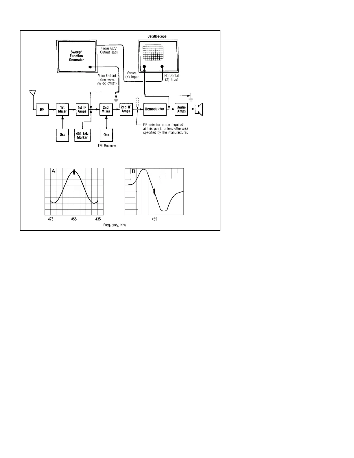
The test set-up of Fig. 17 can be used for
alignment of FM communications receiver
IF’s and discriminators using the 455 kHz IF
f r e q u e n c y. For accurate frequency adjust-
ments, a 455 kHz crystal-controlled marker
source should be used.
1. Use sweep operation and apply signal to
the input of the 455 kHz IF section.
2. When signal at the output of the 455 kHz
IF section is displayed, a response curve
similar to Fig. 17a should be obtained.
The marker “pip” should be in the center
of the response curve.
3. When the output of the discriminator is
displayed, a response curve similar to
Fig. 17b should be obtained. The “S”
curve should be balanced on each side of
the marker “pip”.
In some receivers the IF selectivity is
“packaged”, which means all adjustments are
preset. In this case the receiver alignment can
only be evaluated and verified without adjust-
ment. Where the tuned circuits are adjustable,
the manufacturer’s procedure must be fol-
lowed to ensure that the proper overall
response is obtained.
TESTING DIGITALLOGIC CIRCUITS
Modern function generators are well suit-
ed for testing digital logic circuits. They can
supply square waves, pulses, or gated pulse
trains. On many generators, these waveforms
may be swept in frequency if desired. Using
variable symmetry, narrow clock pulses can
be supplied for breadboarding and design
analysis. A dedicated TTL-level output is
common on most modern units. Its frequency
and symmetry can be varied along with that
of the main output, but its output levels are
always correct for injection into TTL circuits
without adjustment of offset or amplitude.
The standard square wave output of the
generator can also be useful in determining
logic thresholds for a particular TTL circuit.
The user can start by applying a TTL-level
signal, with proper DC offset, and then grad-
ually decrease the amplitude until marginal
operation is produced by the circuit under
test. None: on most units, as amplitude is
decreased, the DC offset will need to be con-
tinually readjusted also.
The square wave output is also useful for
testing CMOS circuits, which may have logic
levels varying from 3V to 18V, depending on
the application. Some function generators
have a CMOS output for convenience, but the
main output can be set up to simulate CMOS
signal conditions.
PRESET FREQUENCYSELECTION
In test and design work where several fre-
quencies are to be used repeatedly, it is con-
venient to be able to preselect these frequen-
cies with a minimum of effort. As shown in
Fig. 18, the VCF feature of many function
generators can be used together with preset
voltages and a frequency selector switch.
1. Construct the circuit shown in Fig. 18.
The voltage labeled “+V” should be a
regulated voltage at or near the maximum
safe input to the VCF input jack as rec-
ommended by the manufacturer. T h i s
limit indicates the voltage value required
for maximum frequency spread on a
given range. Note: applying a higher volt-
age will most likely damage the genera-
tor, and usually won’t provide greater fre-
quency coverage anyway.
2. Consult the instruction manual for the
particular generator to determine whether
its output frequency increases or decreas-
es with an increase in the applied external
voltage.
3. If the frequency increases with positive
voltage changes, set the frequency dial to
the bottom of its rotation (lowest fre-
quency). If frequency decreases with pos-
itive voltage changes, set the dial to the
top of its rotation. Since the VCF input is
summed with the dial voltage, setting the
dial to an end stop insures the the prese-
lected frequencies will be repeatable.
4. Connect the circuit to the VCF input jack,
and connect a frequency counter to the
output of the generator.
Fig. 17. Alignment of FM communications receiver IF’s and discriminators
16
APPLICATIONS
No Amplitude variation can be seen
on FM 2nd IF Signal because of the
limiters and FM modulation does not
use amplitude variations.