The following discussion deals with the
fundamentals of function generator operation
on a block diagram level. While the individ-
ual blocks may be implemented in various
ways depending on the particular generator,
the general principles described are some-
what universal, especially those pertaining to
the basic generator loop. For the discussion,
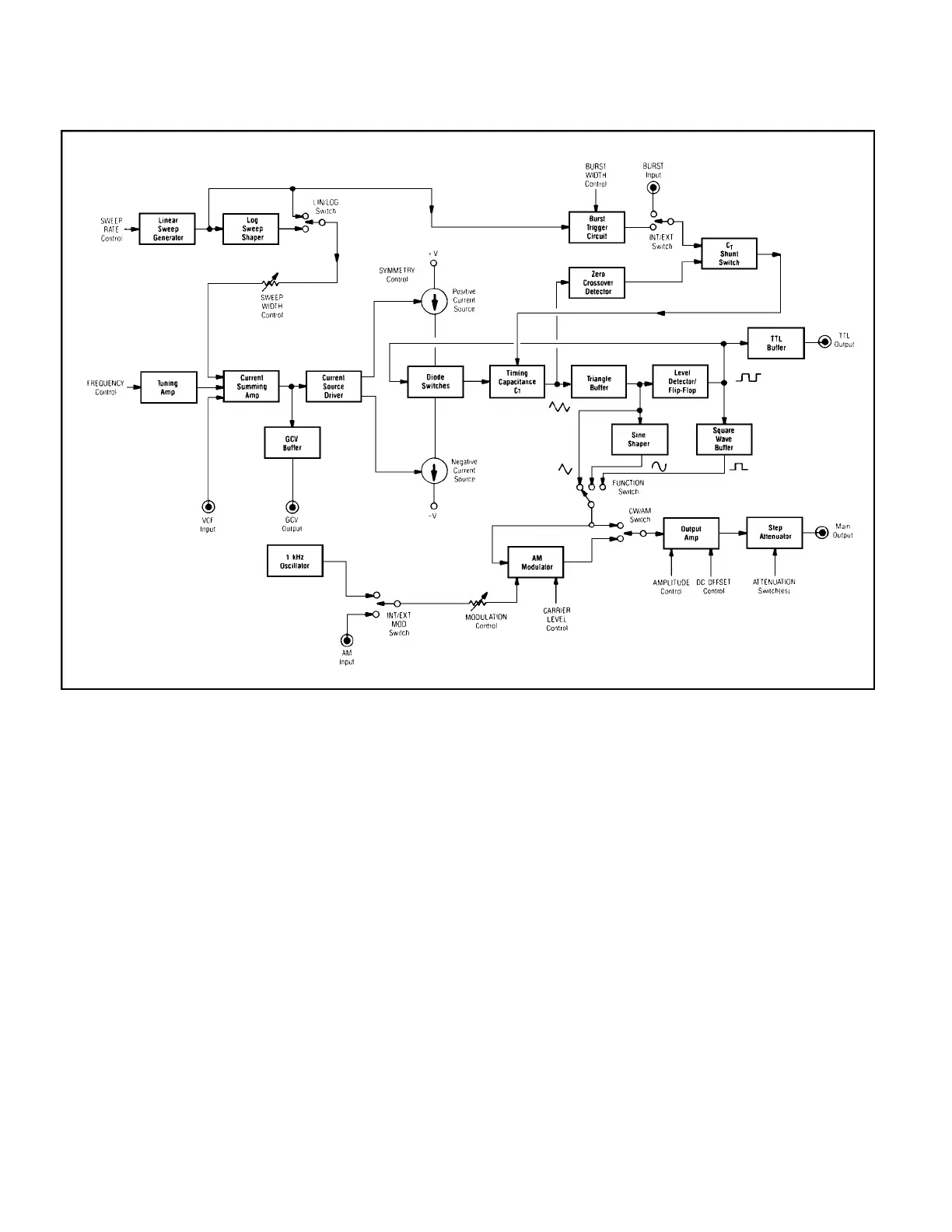
refer to Fig. 2, which depicts the block dia-
gram of a unit with features similar to those
of the hypothetical generator presented in the
T Y P I C A L CONTROLS section of this
guidebook.
Input Circuits
While in the strictest technical sense, a
function generator does not require a signal
input in the manner of a counter or oscillo-
scope, its internal circuitry nevertheless does
possess a “front end”. The basic input is the
DC voltage developed across the FREQUEN-
CYcontrol. As seen in Fig. 2, this is buffered
by a tuning amp which preserves linearity of
the control. This signal is then combined with
other inputs, such as the instantaneous volt-
ages from the VCF (voltage-controlled fre-
quency) jack, and the sweep circuit, in a cur-
rent-summing amplifier. The resulting output,
which is a summation of all pertinent controls
and inputs, is used to control the current
sources in the main generator loop. In some
units, it is also buffered and offered as a GCV
(generator-controlled voltage) output.
Basic Generator Loop
The basic waveform of a function gener-
ator is a triangle wave, developed by alter-
nately charging and discharging a capaci-
tance C
T
via two constant current sources.
This capacitance is the heart of the function
generator; the capacitors used are chosen for
such highly desirable qualities as low dissipa-
tion factor, low temperature coefficient, and
long-term capacitance stability. C
T
is usually
implemented by multiple capacitors, one for
each frequency band, but this discussion will
refer to it as a single component for simplici-
ty.
As seen in Fig. 2, the output of the cur-
rent-summing amp is applied to the current
source driver, which governs the amount of
current in the two sources. This, in turn,
determines the charge/discharge rate of C
T
,
and, ultimately, the frequency of the triangle
wave.
The charge/discharge cycle is regulated
by a feedback scheme wherein the capacitor
voltage is buffered and applied to a level
detector/flip-flop which changes state when-
ever one of two thresholds is reached. The
resulting highs and lows are fed back to a
diode switching arrangement which connects
the capacitor to one of the two current
sources.
Figs. 3 and 4 provide detailed looks at
two implementations of the basic generator
loop. In Fig. 3, the two current sources are
FUNCTION GENERATOR BASICS
Fig. 2 Block diagram of typical function generator circuitry.
6