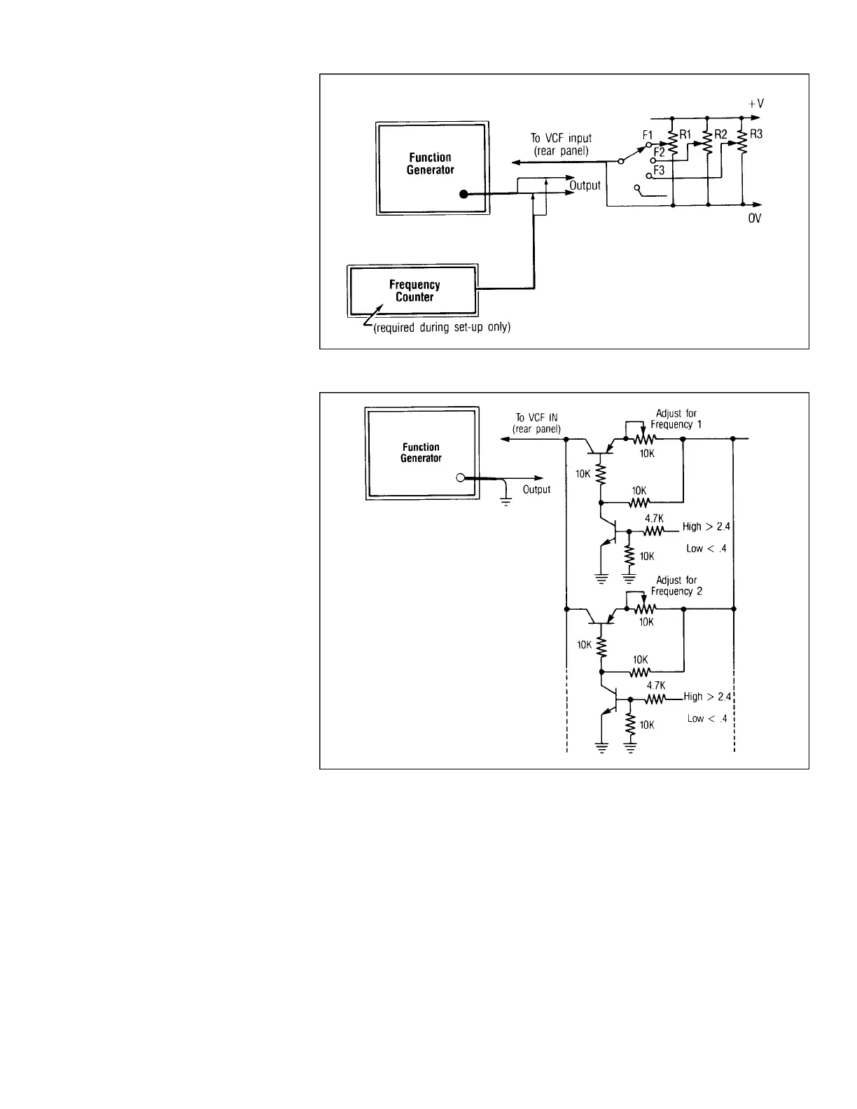
5. With the frequency selector switch in the
F1 position, adjust R1 for the desired fre-
quency as observed on the counter.
Repeat this for the other frequencies
desired.
6. After the initial set-up, whenever this cir-
cuit is used for automatic frequency
selection, the frequency dial on the gen-
erator must be placed at the same end of
rotation for repeatability.
DIGITALFREQUENCYSELECTION
Frequencies can be switched electronical-
ly by using the set-up shown in Fig. 19. The
preset voltages can be digitally selected and
applied to the VCF input jack on the genera-
tor. Although provisions for two frequencies
are shown, additional frequencies can be
added using redundant circuits. This is con-
venient in frequency shift keying (FSK) sys-
tems.
As with “Preset Frequency Selection”
above, “+V” in the circuit should be at or near
the maximum safe limit specified for the
VCF input jack by the manufacturer, and a
counter should be connected to the generator
output for initial frequency calibration.
Whenever the circuit is used thereafter, the
dial should be set to the same end stop for
repeatability.
TESTING TONE BURST DECODERS
A tone burst decoder requires a specific
tone frequency, such as 2250 Hz, for a spe-
cific minimum period of time, such as 120
milliseconds, before it will provide an output.
This delay prevents voice signals or other
random on-frequency signals from falsely
activating the decoder. A function generator
equipped with tone burst capability can gen-
erate the signals necessary to test the delay
time, as well as the frequency response and
sensitivity of tone burst decoders.
The following procedure, along with Fig.
20, describes the typical testing method for
these devices.
1. Connect equipment as shown in Fig. 20.
With the generator initially in the contin-
uous run mode, set its range and frequen-
cy to the decoder’s acceptance frequency.
This should be found in the manufactur-
er’s service literature, or may be marked
on the unit. Use a frequency counter if a
high degree of accuracy is required.
2. Set the generator to tone burst mode, and
select internal gating.
3. Using a dual-trace oscilloscope, display
the decoder input signal on one trace and
its output on the other. Synchronize the
scope to the beginning of the tone burst
signal.
4. Adjust the duration of the tone burst to
equal or slightly exceed the specified
turn-on delay time of the unit under test.
5. Adjust the repetition rate of the tone
burst, allowing sufficient time between
bursts for the decoder to fully return to its
standby condition. The repetition period
can be measured on the oscilloscope.
6. The decoder’s turn-on delay period can
also be measured on the scope. This is the
time period from the beginning of the
tone burst until the decoder output
changes stated. Decoder turn-off delay
can also be measured. This is the time
period from the end of the tone burst until
the decoder output reverts to the off state.
Both intervals are shown in Fig. 20.
Fig. 19. Digitally programmed frequency selection.
17
APPLICATIONS
Fig. 18. Preset frequency selection.
OFF
ON
OFF
ON