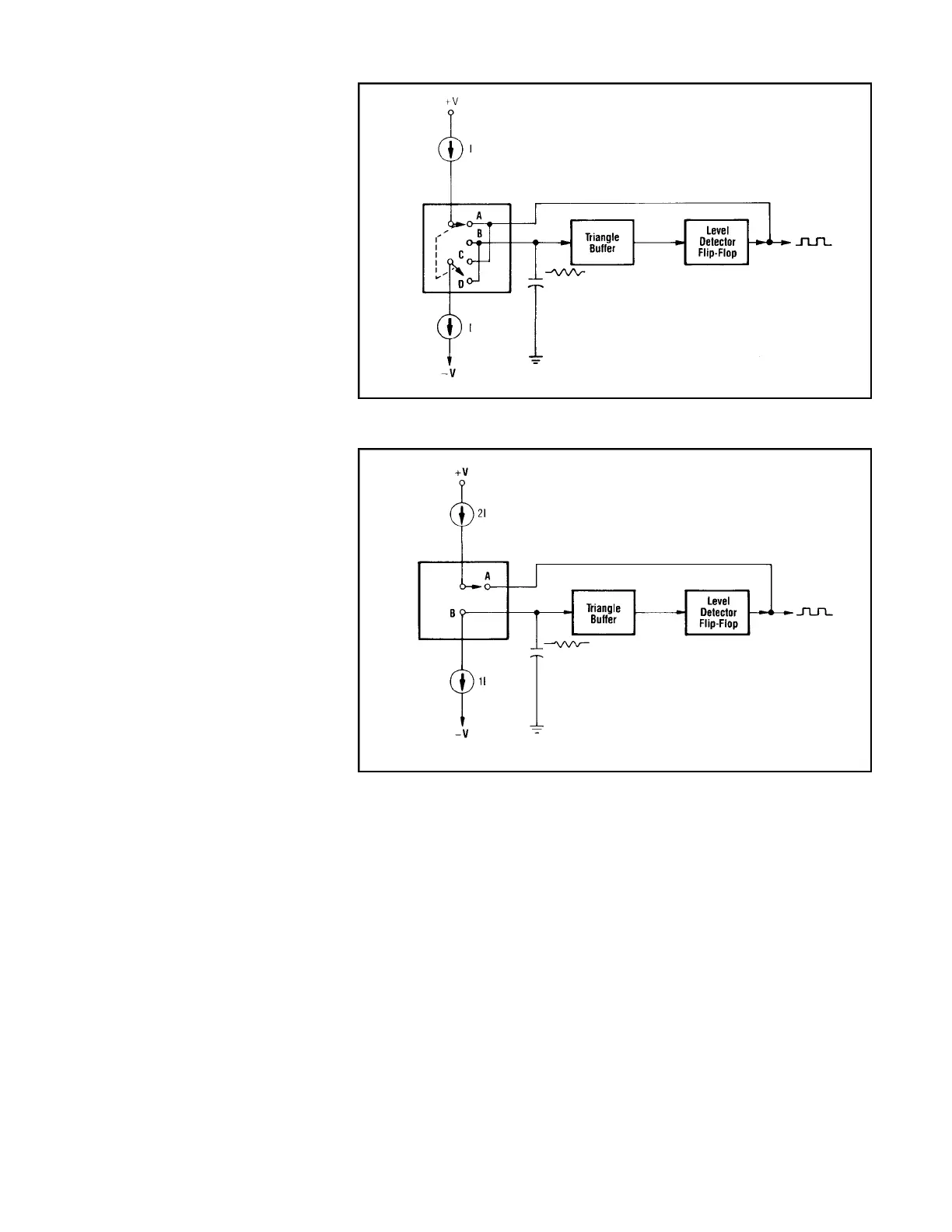
each of the same value, “I”. The diode
switching arrangement, which usually con-
sists of a four-diode bridge, is represented
figuratively by a double-pole, double-throw
switch controlled by the flip-flop output. In
the position shown, “AD”, the flip-flop is in
the low state, and it sinks all current from the
positive source. The negative current source,
on the other hand, is connected to the capaci-
tor and is discharging it at this point in time.
When the capacitor voltage reaches the low
threshold of the flip-flop, the “switch” will
change to position “BC”. Then the positive
current source will feed the capacitor, while
the negative source sinks current from the
flip-flop’s “high”.
Fig. 4 presents a simpler “switch”
arrangement, usually implemented merely by
two diodes. Here, however, the positive cur-
rent source delivers twice the current of the
negative source. In position “A”, as shown,
the flip-flop output is low, and it sinks all the
positive current. The negative current source,
which is always connected to the capacitor, is
discharging it at a current rate of “I”. In posi-
tion “B”, produced by a “high” from the flip-
flop, both sources are connected to the capac-
itor, resulting in a net current of “I” into it.
The capacitor is thus charging at a rate equal
to its previous discharge rate.
Variations in symmetry can be achieved
by altering the amount of current flow in one
of the current sources. Coarse changes in fre-
quency (range changes) can be effected by
altering the flow in both sources, or by chang-
ing the value of C
T
. Some generators drasti-
cally change C
T
by applying the triangle
waveform, inverted, to the opposite end of
the capacitor, thus producing an effective
capacitance “multiplier”.
Function Selection
Most generators offer three output func-
tions: triangle, square, and sine wave. The tri-
angle is simply the buffered output of the
capacitor voltage, passed to a final output
amplifier. The square wave is obtained by
taking the T T L output of the level
detector/flip-flop, shifting its DC bias for
symmetry about zero, and sending it to the
output amp. The sine wave is produced by
applying the buffered triangle to a sine
shaper, which may consist of a transistor
array or several diode bridges. The resulting
sinusoidal waveform is sent to the output
amp. The FUNCTION switch determines
which of the three waveforms is selected.
Output Stages
The output amplifier may be a simple cir-
cuit with relatively few transistors, or it may
be a complex configuration incorporating
separate pre-amp and power amp sections. In
either case, the output AMPLITUDE control
is usually a gain adjustment in this amplifier.
Similarly, the DC OFFSET control is imple-
mented as a bias adjustment in this circuit.
The attenuator, if one is provided, is a set
of precision resistances selected to provide a
prescribed amount of attenuation without
changing the output impedance (typically
50Ω).
Additional Circuitry
The preceding discussion describes the
basic circuits required in all function genera-
tors. However, many units are equipped with
additional features, which are included in Fig.
2. A discussion of these features follows.
Sweep Circuit
The output frequency of the generator is
determined by the various signals applied to
the current summing amp. To produce a fre-
quency sweep, a ramp voltage must be
applied. This can be externally generated and
fed into the VCF input, or can be created
internally, as follows.
As shown in Fig. 2, a sweep generator
produces a linear ramp whose repetition rate
is governed by the SWEEP RATE control.
The ramp is fed to a circuit which changes it
from linear to logarithmic. Both waveforms
are applied to the LIN/LOG switch, which
selects one and passes it to the current sum-
ming amp.
Width of the frequency sweep is directly
related to the width of the ramp. This can be
FUNCTION GENERATOR BASICS
7
FIG. 3 Basic Generator Loop.
FIG. 4. Basic Generator Loop - Alternate Implementation.