INTRODUCTION
Because of the wide range of function
generators currently available, and the wide
array of features which they offer, the inven-
tive user can undoubtedly devise many more
applications than can be covered here.
Therefore, this section endeavors to cover
some basic applications using features found
on the hypothetical generator presented in the
T Y P I C A L CONTROLS section of this
guidebook. It is hoped that the user can utilize
these basic ideas, perhaps improvising or
improving upon them as the particular situa-
tion dictates. The reader should note that
these descriptions have been generalized to
some degree to account for differences in
specific generators.
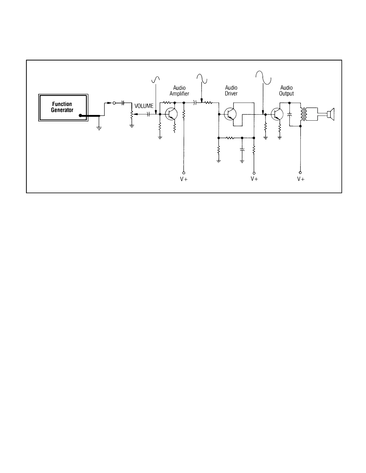
TROUBLESHOOTING BY S I G N A L
TRACING
One of the most common methods of
troubleshooting defective audio equipment is
to inject a signal from a function generator at
the input of the device under test. An oscillo-
scope is then used to check the output at each
stage, starting nearest the input and moving
toward the output. The stage which has no
output or distorted output is presumed to be
defective. A typical application is presented
in Fig. 6. The input signal is usually a sine
wave of low enough amplitude so as not to
produce undesired clipping in later stages.
Also, there is usually no DC offset present,
although, as shown in the figure, most ampli-
fiers incorporate an input capacitor to block
any DC component.
The technique is equally applicable to
non-audio equipment. Most function genera-
tors can produce signals up to 1 MHz, with
some models capable of 5 MHz or higher.
TROUBLESHOOTING BY S I G N A L
SUBSTITUTION
A variation on the signal tracing tech-
nique is to inject an audio signal at various
points in the circuit under test, to substitute
for the normal signal. In this technique, the
signal is first injected nearest the speaker and
is moved toward the audio input one stage at
a time until no sound is heard from the speak-
er. The stage that produces no sound is pre-
sumed to be defective.
One precaution: make sure that the DC
offset matches the normal operating voltage
at each point of signal injection. Improper DC
offset could bias a normally operating stage
to cutoff and make it appear defective; it
could also damage the circuit under test. A
coupling capacitor may be used to block the
DC offset and allow the signal to float at the
DC level of the point of injection if desired.
The signal amplitude should simulate the
normal signal levels used in the circuit where
signal is being injected.
This technique is also applicable to non-
audio equipment. Connect an oscilloscope,
voltmeter, or any other device which will
indicate the presence or absence of output.
If the equipment under test is already
handling one or more signals that could be
confused with the test signal, use sweep or
tone burst operation on the function generator
to produce unique sounds or signals. These
should be easily distinguishable from any
other signals that may be present.
USING A FUNCTION GENERATOR AS
A BIAS AND SIGNALSOURCE
Most modern function generators are able
to superimpose a DC offset voltage on their
AC signal output. As shown in Fig. 7, this
capability can be used to bias a transistor
amplifier under test as well as furnish the AC
component of the input signal. By observing
the amplifier output on an oscilloscope, the
amplitude and bias of the transistor can be
optimized for maximum undistorted output.
By varying the DC offset, the effects of vari-
ous types of bias (class A, B, and C) can be
determined.
9
APPLICATIONS
FIG. 6. Possible signal tracing points in a simple amplifier.