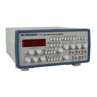
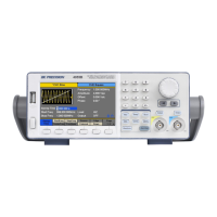
Fig. 1 depicts a hypothetical function
generator whose front panel includes most of
the typical jacks and controls found on mod-
ern function generators, although names of
the individual controls may vary from unit to
unit. Whereas this figure assigns one function
to each control, actual units often combine
multiple functions in single controls for sim-
plicity of panel layout.
1. POWER Switch. Turns power on and
off.
2. DUTY CYCLE Switch. When engaged,
enables operation of DUTYCYCLE con-
trol (7).
3. CMOS LEVELSwitch. When engaged,
changes the TTLsignal to CMOS signal
at the TTL/CMOS jack and enables
operation of CMOS LEVELControl (8).
4. DC OFFSET Switch. When engaged,
enables operation of the DC OFFSET
control (11).
5. -20dB Switch. When engaged, the signal
at the OUTPUT jack is attenuated by 20
dB.
6. RANGE Switch. Selects output frequen-
cy range. Eight ranges from 2 Hz to 20
MHz. Switch indicates maximum fre-
quency of range and is adjusted with
COARSE FREQUENCY control to 0.1
times the maximum. For example, if the
200 kHz range is selected, the output fre-
quency can be adjusted from 20 kHz to
200 kHz.
7. DUTY CYCLE Control. Activated by
the DUTY CYCLE Switch (2). Rotation
from center position adjusts the duty
cycle of the main OUTPUT signal and
TTL/CMOS signal.
8. CMOS LEVEL Control. Rotating this
control clockwise increases the amplitude
of the CMOS signal at the TTL/CMOS
jack.
9. FUNCTION Switch. Selects sine,
square or triangle waveform at OUTPUT
jack.
10. OUTPUTLEVELControl. Controls the
amplitude of the signal at the OUTPUT
jack. Output level can be decreased by
approximately 20 dB with this control.
11. DC OFFSET Control. Activated by the
DC OFFSET Switch (4). Clockwise rota-
tion from center changes the DC offset in
a positive direction while counterclock-
wise rotation from center changes the DC
offset in a negative direction.
12. VCG/MOD INPUTJack. Controlled by
MODULATION OFF/ON Switch (33).
When MODULATION OFF is selected,
jack is the Voltage Controlled Generator
input and permits external control of gen-
erator output frequency by a DC voltage
input at this jack. A positive voltage will
decrease frequency. When MODULA-
TION ON is selected, jack becomes mod-
ulation input source.
13. OUTPUT Jack. Waveform selected by
FUNCTION Switch as well as the super-
imposed DC OFFSET voltage is avail-
able at this jack.
14. BURST INPUT Jack. Input for external
gating signal for Burst operation.
15. TTL/CMOS Jack. T T L or CMOS
square wave, depending on the position
of the CMOS LEVELswitch (3) is output
at this jack. This output is independent of
the OUTPUT LEVEL and DC OFFSET
controls.
16. EXT. COUNTER INPUT Jack. Input
for external frequency measurements.
17. BURST WIDTH Control. Adjusts the
duty cycle of the internal burst gate.
18. % MODULAT I O N C o n t ro l . A d j u s t s
the percentage of AM or FM modulation.
19. BURST OFF/ON Switch. Selects exter-
nal or internal burst gate. Continuous out-
put is obtained with switch in the OFF
position and no external burst gate is
applied.
20. START/STOP Switch. Enables adjust-
ment of the starting and stopping sweep
frequencies. The actual adjustment is per-
formed by the SWEEP S TA RT a n d
S W E E P S TO P controls (29 and 27).
START/STOP selection is enabled only
when the SET/RUN switch (21) is set to
SET.
21. RUN/SET Switch. Selects sweep set or
sweep run operation. In the SETposition,
the starting or ending sweep frequency is
continuously present at the output. In the
RUN position, the generator sweeps
between the low and the high frequencies
at a rate set by the SWEEPTIME control.
22. S W E E P E X T / I N T S w i t c h . W h e n
engaged (INT) enables the sweep mode
of operation. Sweep rate is controlled by
SWEEP TIME control (25) and sweep
length is controlled by the SWEEPSTOP
control (27) and the start frequency is
controlled by the SWEEPSTART control
(29). When released (EXT), allows exter-
nal control of generator output frequency
by a DC voltage input at the VCG/MOD
INPUT jack (12).
23. S W E E P LIN/LOG Switch. W h e n
engaged (LOG) selects logarithmic
sweep characteristic and when released
(LIN) selects a linear sweep characteris-
tic.
24. CNTR INT/EXT Switch. Selects the
input source for the counter input.
25. SWEEPTIME Control. In sweep mode,
rotation determines amount of time to
sweep from the start frequency to the stop
frequency.
26. FINE FREQUENCY Control. Vernier
adjustment of the output frequency for
ease of setting frequency.
27. S W E E P S TO P C o n t ro l . Adjusts the
ending sweep frequency.
28. COARSE FREQUENCY C o n t ro l .
Coarse adjustment of the output frequen-
cy from 0.1 to 1 times the selected range.
29. SWEEP START Control. Adjusts the
starting sweep frequency.
30. GATE LED.Indicates when the frequen-
cy counter display is updated. When the
200K through 20M ranges are selected,
the LED will flash 10 times per second
(every 0.1 seconds). When the 20 through
20K ranges are selected, the LED will
flash every 10 seconds. As the LED turns
off, the display is updated.
BASIC FUNCTION GENERATOR CONTROLS
4