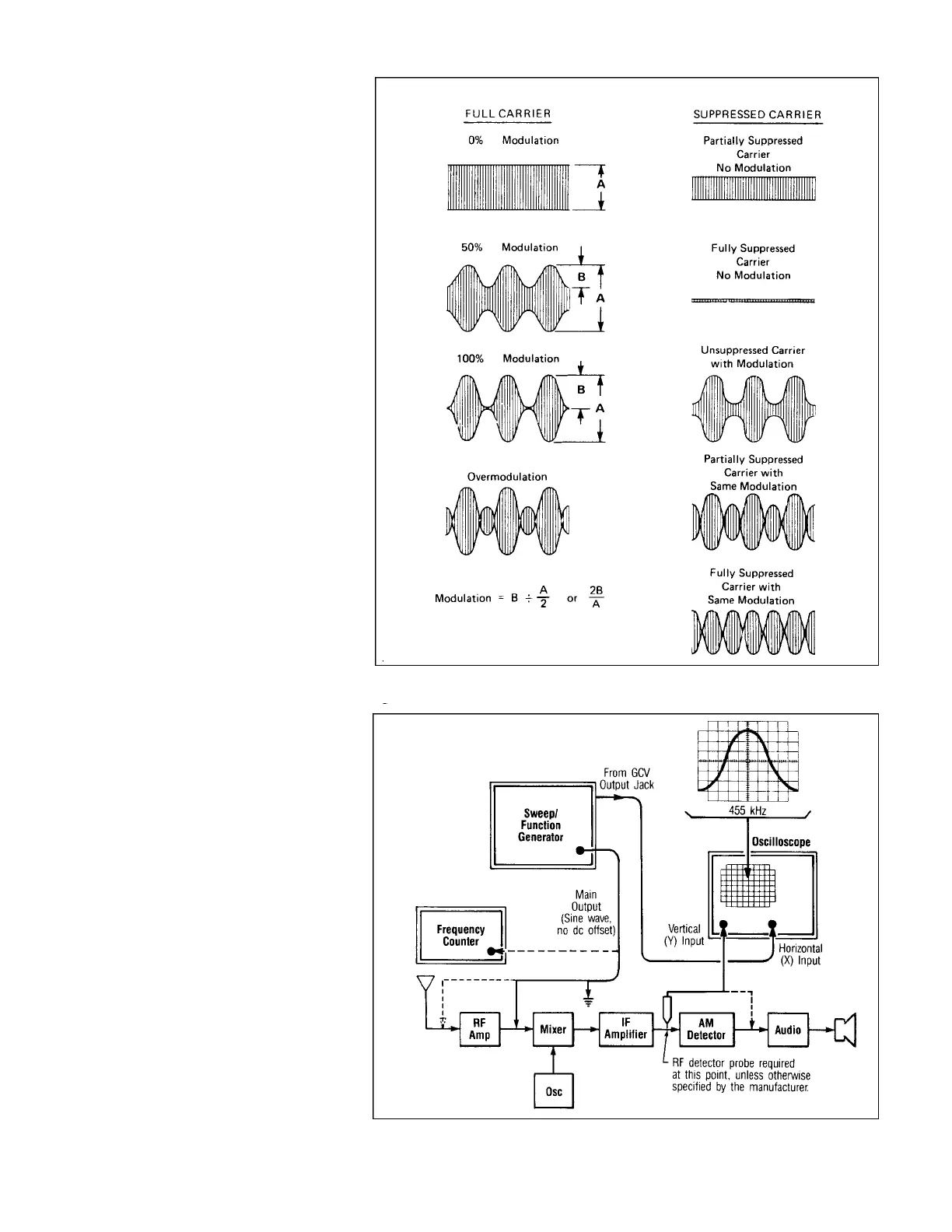
suppressed carrier. When a signal is ampli-
tude-modulated, two “sidebands” are created
on either side of the carrier frequency. Each
of these sidebands contains all of the modu-
lating information; consequently, either the
carrier alone or the carrier and one sideband
can be suppressed for reduced power con-
sumption by the radio transmitter. These two
modes of operation are known as double-
sideband (DSB) and single-sideband (SSB),
respectively. Some function generators pro-
vide a carrier level control which allows par-
tial or complete suppression of the carrier for
double-sideband operation. The figure shows
the generator output for partial and complete
carrier suppression, with and without modu-
lation.
AM RECEIVER ALIGNMENT
1. Use the test set-up of Fig. 16, with the
generator set to produce a linear sweep
display.
2. If a precise center frequency and band-
width is required, a frequency counter
should be used during set-up. Function
generators with built-in frequency coun-
ters (digital display) simplify this step.
Before sweep operation begins, set the
frequency dial on the generator to obtain
the desired frequencies of interest on the
counter and place markers on the oscillo-
scope screen using a grease pencil or
china marker.
3. The signal can be injected either at the
mixer (455 kHz) or at the antenna,
depending on the frequency capability of
the generator. When injecting the 455
kHz signal at the mixer input, the local
oscillator must be disabled.
4. When the IF response is observed at the
input to the AM detector, an RF detector
probe is required unless a demodulated
point is specified by the manufacturer.
5. The IF amplifier tuning adjustments can
be performed as required to obtain the
desired IF response curve. Often, each
tuned circuit is adjusted for maximum
amplitude at the IF center frequency.
However, some IF amplifiers are stagger-
tuned to achieve the desired bandwidth.
External sweep may be used if desired for
sine wave or other sweep patterns. Connect
the external sweep voltage source to the VCF
input jack of the generator. The external
sweep voltage should also be applied to the
horizontal input of the oscilloscope. To set up
frequency markers, a variable DC power sup-
ply may be fed into the VCF input jack and
APPLICATIONS
15
Fig. 15. AM modulation and suppressed carrier waveforms.
Fig. 16. AM receiver alignment