17
output is connected to the positive end (+) of the load and the negative lead (-) of the DC
output is connected to the negative end (-) of the load. When this sensing mode is selected, the
wires connecting between DC outputs to the load must be as short as possible. The local sense
is the default configuration with shorting bars connected between (S+) to (+) and (S-) to (-).
DO NOT disconnect the wires if remote sense is not used. Doing so will cause
erratic behavior and may damage the power supply under certain conditions.
Never connect any power source into any of the four terminals at any time during
operation.
When output is enabled, DO NOT use your hands to touch the terminals or the
screws that are designed to tighten wires to the terminals. Doing so may create a
shock hazard under high voltage output conditions.
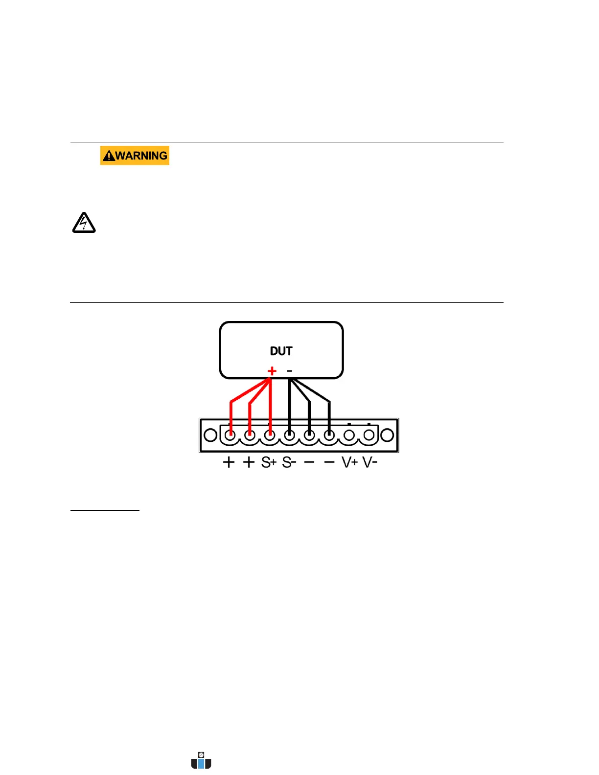
Figure 7 - Remote Sense Connection
Remote Sense
When remote sense is selected, the positive sense (+S) and positive lead (+) of the DC output
are connected to the positive end (+) of the load, whereas the negative sense (-S) and negative
lead (-) of the DC output are connected to the negative end (-) of the load. Note: when using the
front output terminals of the power supply, only the rear S+ and S- terminals need to be
connected.
To enable remote sense, follow the steps below:
1. Power OFF the supply and disconnect all loads and cables connected to it.
2. Use a small flat blade screwdriver to loosen the wire connection connected between +
and S+ and S- and -.
3. Connect the S+ to the DUT’s positive (+) terminal, and connect the S- to the DUT’s
negative (-) terminal.
www.calcert.com sales@calcert.com1.888.610.7664
0
5
10
15
20
25
30
 Loading...