2.3 Connect the probes
It is recommended to test the Bluelab pH Controller prior to mounting. Attach both the
pH and Temperature probes to the controller, plug in the power adaptor, place probes
into solution and wait a few minutes for the readings to stabilise.
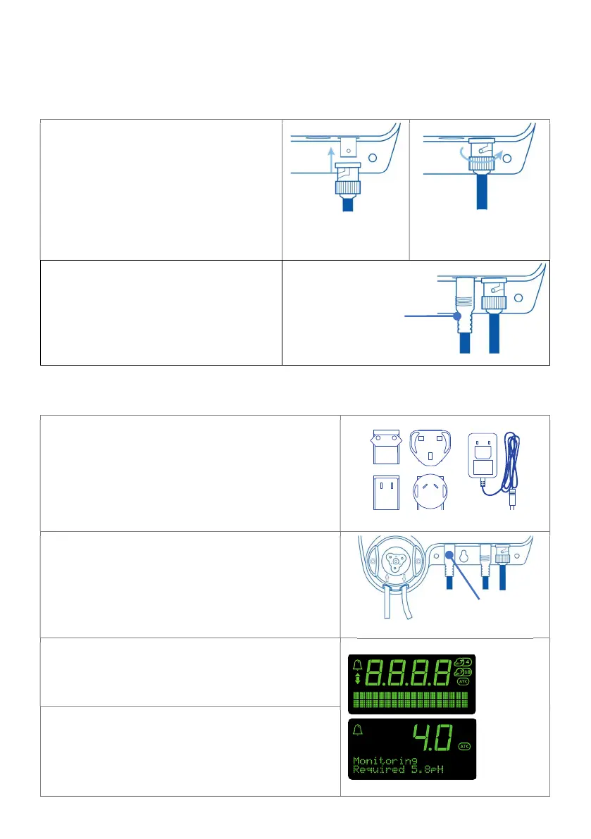
pH Probe
Line up the lugs of the BNC probe
connector with the receptacle on the
Bluelab pH Controller labelled ‘pH’.
Fasten securely by pushing the pH
probe connector on and twisting one
quarter turn.
Push connector Twist & attach
Temperature Probe
Fully insert the temperature probe
connector into the Bluelab pH
Controller receptacle marked ‘ATC’.
2.4 Power up
Select and connect the appropriate mains plug
adaptor for your region to the power supply
unit.
Connect the power adaptor into the Bluelab pH
Controller receptacle marked ‘PWR’.
Plug the power adaptor into a mains outlet and
switch it on. The Bluelab pH Controller will
complete a display test sequence.
The default setting, is ‘monitoring’ mode.
Note: pH calibration must be completed before
the first use, see section 5.0 to ensure pH
readings are accurate.
probe connection
adaptor