7. Run the cables through the required cable guides and grommets, and then install the cable guides on the frame to close the
openings at the head tube (5). The 4 possible combinations are listed below.
Combinations / Description Required parts Part N°
A Mechanical (USA and EU standard) 1, 2, 3, 6 212487
B Mechanical (UK standard) 1, 2, 3, 6 212487
C Di2 (USA and EU standard) 5, 6, 7 212488
D Di2 (UK standard) 1, 4, 7 212488
2 Shifting cable grommet (spare part) 2 212490
3 212496 3 212491
7 Di2 grommet (spare part) 7 212489
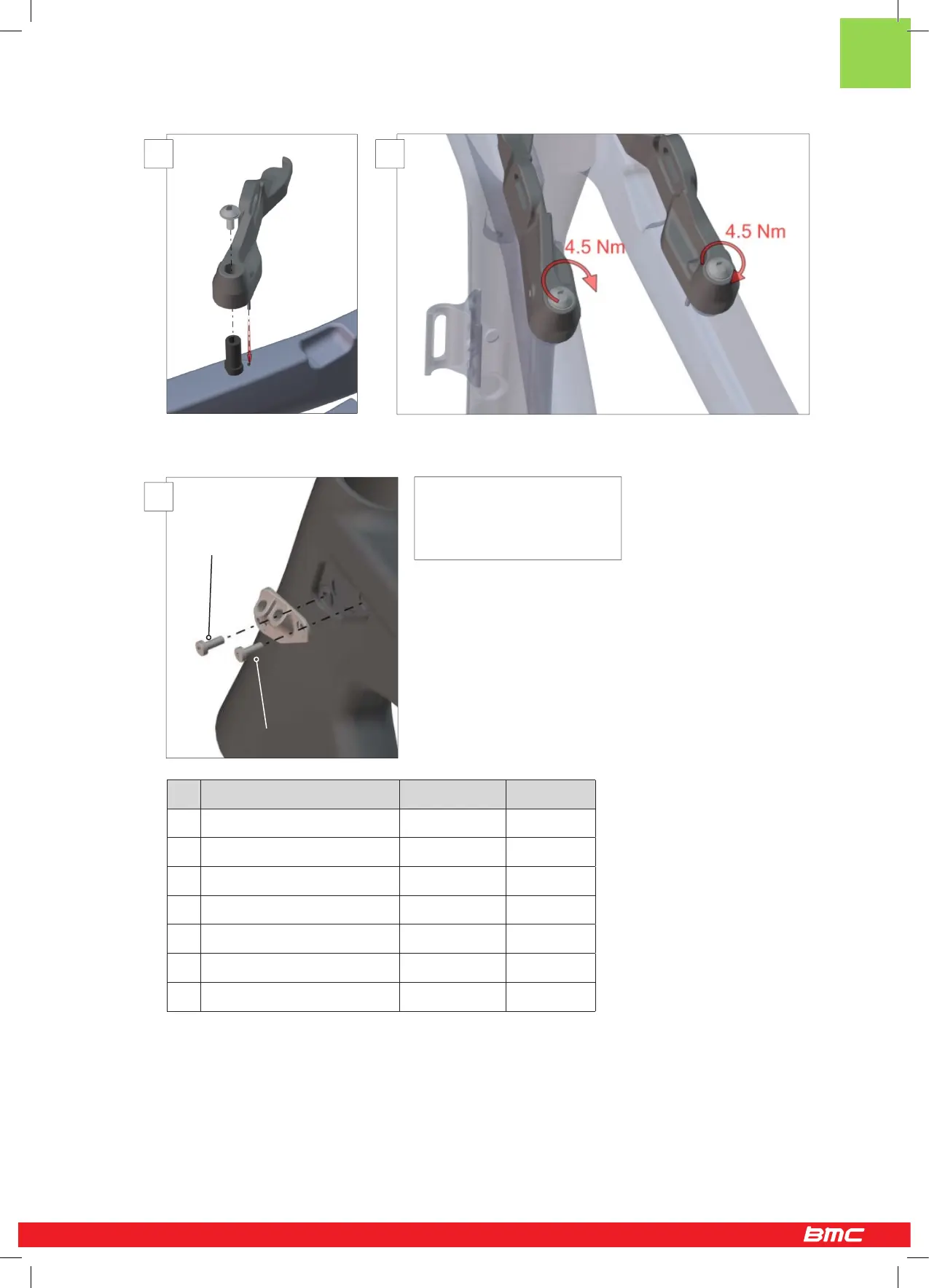
Important: Note that the shorter
screw (4.5mm) goes to the front,
the longer screw (8mm) goes to
the back.
Shorter screw
Longer screw
3 4
5
11 / 12