Toplift / Toplift ECO
12 92023200095
4 ASSEMBLY OF THE HOIST
4.1 Indications for safety
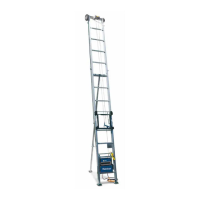
Make yourself familiar with the surroundings before
assembling the TOPLIFT. Pay attention to the soil
bearing and separate the construction site from pub-
lic access. The working area of the TOPLIFT has to
be separated by a fence. This fence has to consist of
at least two horizontal elements which have to be
marked with contrasting colours (for exp. red/white).
picture 4-1 (All dimensions in meters)
4.2 Estimation of the rail length
Take vertical lifting height and add approximately
20% for inclination. Increase to full meter.
4.3 Assembly of the rails
1. Place foot section on the ground and fit feet or
undercarriage.
2. Introduce carriage with rollers onto the rail.
picture 4-2
Hint! The knurled cams of the broken rope device
located on the upper axle have to be released
by raising the linkage.
3. Slide the carriage to the bottom of the foot sec-
tion.
4. Place the extensions of 2 or 1 m on the ground.
5. Join the extensions.
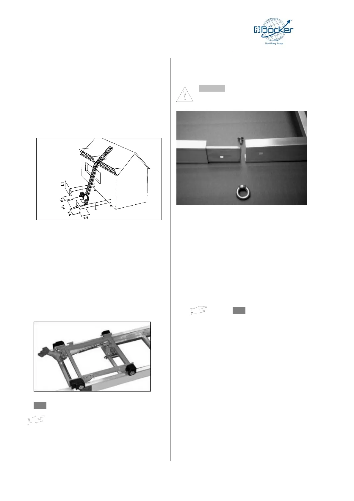
Attention! The ring nuts are on the outside
of the rails!!!
picture 4-3
6. Place the head section on the rails and tighten as
well.
7. Tighten all ring nuts.
4.4 Setting up the rail section
Up to 8 m length, the rail can be set up by hand and
brought in the right inclination as a ladder.
Anchor the feet with pins.
Up to 13 m length, the rail can be raised from above
by a rope.
Hint! The rope has to be at-
tached in the middle of the
head section or upper end of the rail to
avoid that the hoist will not tilt sideways.
Push along the rail section until the right inclination
has been reached.
Above 13 m length, assemble the rail on the ground
and raise as above until vertical.
1. Raise the rails about 2.30 m.
2. Add further sections to the bottom of the rail.
3. Finally add the foot section with carriage fitted.
4. Incline to correct angle, then fit adjustable sup-
port.