Toplift / Toplift ECO
15 92023200095
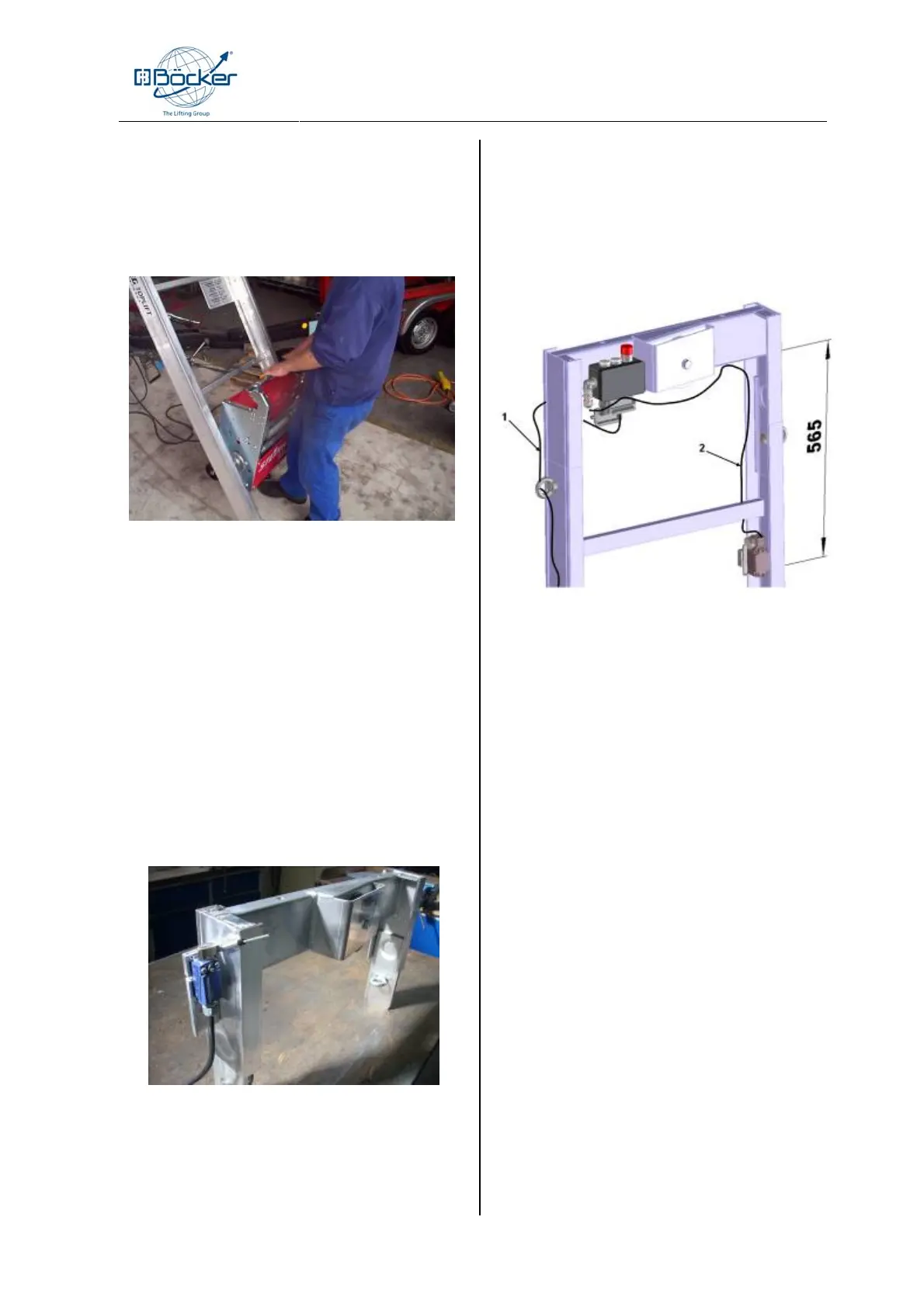
4.13 Setting up the drive unit
The drive unit is to be put onto the lower rung of the
foot section. Make sure that the drive unit is placed in
the middle of the ladder rung (picture 4-9)
Neues Bild
picture 4-9
1. Put the drive unit into the rail and unlock it by pull-
ing up the handle.
2. At lock-in device in position “unlocked” put the
drive unit with energy into the next rung.
3. Check that the locker hooks on the rung.
4. Put the 5-pole plug of the hand control in the
middle socket on the drive unit.
5. Put the 3-pole plug of the limit switch cable in the
upper socket on the drive unit.
4.14 Assembly and adjustment of the
upper limit switch (without MV)
picture 4-10
1. Screw the limit switch holder on to the head
section.
2. Take limit switch cable up to the head section
and fix it to the holder with the wing-screw.
3. Lead the limit switch cable down the rails and
fix it to the eye screws of the rails.
4. Wind the remaining cable carefully and fix it to
the side of the drive unit.
4.15 Assembly and adjustment of the
upper limit switch TOPLIFT Furni-
ture (MV)
picture. 4-11
1. Screw the limit switch holder with the limit
switch already mounted and the limit switch
cable (2) to the first rail underneath the head
piece.
2. In doing so, please observe the measure-
ments given in Fig. 4-11.
3. Now fasten the limit switch holder to the rear
side of the rail using the knurled screw, so
that it can no longer be moved.
4. The position of the limit switch roll must be
adapted to the respective furniture car-
riage.(Fig. 4-12)
5. Direct the connecting cable (1) behind the
head piece and guide it downwards.
6. Wind the remaining cable carefully and fix it to the
side of the drive unit.