Aufstellung.pm6.5 - USA
Page 3.6
Installation
BOGE Operating instructions for S 40-2...S 341 / SF 40-2...SF 220 series screw compressors
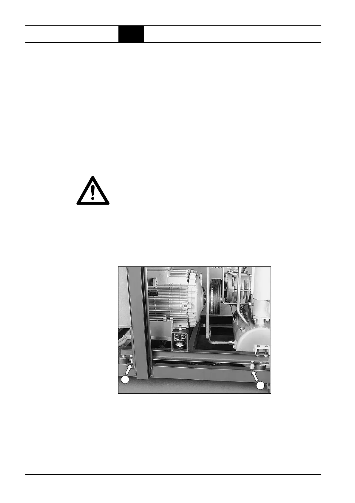
Removing the transport
securing bolts
Fig. 3.1: Removing the transport securing bolts Note:
3.3 Installation
Note: Demonstration example. Compressor may only be operated with the switch cabinet
closed and all panels fitted.
Connecting the
cooling water (option)
The pipework for the cooling water circuit in the compressor is completely
installed at the factory.
Only the following work must be performed during installation:
– Check, whether the water supply has the required data and whether the
cooling water quality is adequate (see page 2.10).
– Connect the cooling water supply and discharge line to the water supply.
The following component parts must be provided by the customer for cooling
water installation:
– Dirt traps
The dirt trap at the cooling water inlet protects the cooling units against
sediment collecting. Pore width: max. 0.6 mm
– Expansion vessel and safety valve
ATTENTION!
If the stop valves in the supply and discharge lines are simultaneously closed
in a closed cooling system, an enclosed room will result. If the water heats
up in this room, it will expand and the pressure will increase.
Install an expansion vessel and a safety valve to prevent damage to the
cooling units.
The frame of the drive unit is bolted to the base frame for transport.
Remove the four red marked screws and (each two on the longitudinal
side) together with the space collars.
1
2
 Loading...