Fliess.pm6.5 - USA
Page 6.3
Appendix
BOGE Operating instructions for S 40-2...S 341 / SF 40-2...SF 220 series screw compressors
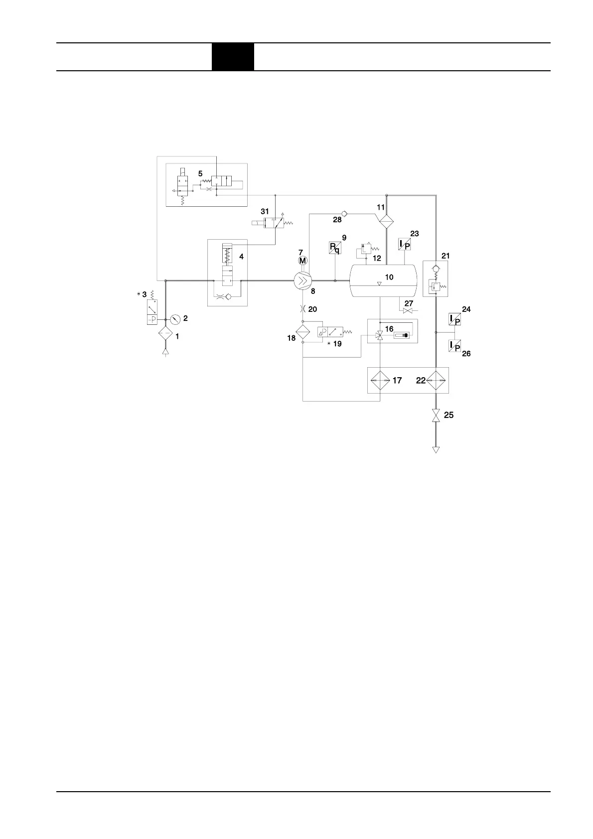
6.1 Flow chart
Air cooled version, frequency-controlled
1 = Suction filter
2 = Maintenance display
3 = Vacuum switch (for suction filter monitoring) *
4 = Suction controller
5 = Air relief and regulation control valve
6 = Pressure switch (for rotational direction,
system relief and V-belt monitoring)
7 = Drive motor
8 = Air end
9 = Final compression temperature display and switch
10 = Combined compressed air/oil receiver
11 = Oil separator
12 = Safety valve
13 = Differential pressure switch
(for oil separator monitoring) *
14 = System pressure switch
(for system pressure build-up and monitoring) *
15 = Safety pressure switch (for pressure limitation) *
16 = Thermostatic oil control valve
17 = Oil cooler
18 = Oil filter
19 = Differential pressure switch
(for oil filter monitoring) *
20 = Oil throttle
21 = Minimum pressure check valve
22 = Compressed air after-cooler
23 = Operating pressure switch
24 = Pressure gauge (line pressue)
24.1= Pressure gauge (system pressure)
25 = Stop valve, compressed air outlet
27 = Stop valve, oil drainage
27.1= Stop valve, oil drainage
(oil cooler, 75 – 250 kW)
28 = Check valve drainage line
(to 75 kW)
* = Option
Air IN
Compressed
air OUT
 Loading...