The behavior of the positioning after the required position of the drive is reached can
be defined via the
Activity after positioning
463 parameter.
Activity after positioning 463
0 - End positioning
The drive is stopped with the stopping behavior
of Operation mode 630.
1 - Wait for positioning signal
The drive is stopped until the next signal edge;
with a new edge of the position signal, it is ac-
celerated in the previous direction of rotation.
2 - Reversal by new edge
The drive is held until the next signal edge; with
a new edge of the position signal, it is accelerat-
ed in the opposite direction of rotation.
3 - Positioning; off
The drive is stopped and the power output stage
of the inverter is switched off.
4 - Start by time control
The drive is stopped for the Waiting time 464;
after the waiting time, it is accelerated in the
previous direction of rotation.
5 - Reversal by time control
The drive is held for the Waiting time 464; after
the waiting time, it is accelerated in the opposite
The position reached can be maintained for the Waiting time 464, then the drive is
accelerated according to operation mode 4 or 5.
464
Waiting time 0 ms 3600,000 ms 0 ms
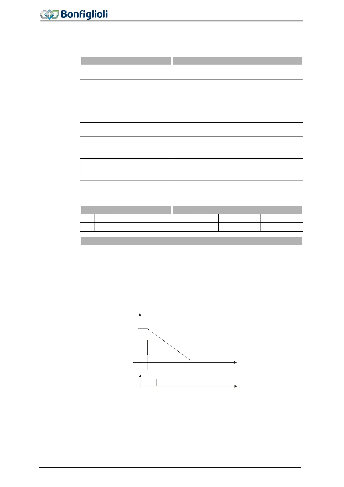
Positioning, Operation Mode 458 = 1
The diagram shows how the positioning to the set positioning distance is affected.
The positioning distance remains constant at different frequency values. At the refer-
ence point, the position signal S
Posi
is generated. Starting from frequency f
max
positioning is affected at the set Deceleration (clockwise) 421
value f
1
, the frequency remains constant for some time before the drive is stopped at
the set deceleration.
If, during acceleration or deceleration of the machine, positioning is started by the
signal S
Posi
, the frequency at the time of the positioning signal is maintained.
f
f
max
f
1
S
pos i
U
U
min
t
Digital Input
6
Deceleration (Clockwise)
421
146 Operating Instructions ACU 06/13
 Loading...
