10.2.3 Magnetizing Current
The Rated magnetizing current 716 is a measure of the flux in the motor and thus of
the voltage which is present at the machine in no-load condition depend
speed. The guided commissioning determines this value at about 30% of the Rated
current
371. This current can be compared to the field current of an externally excit-
ed direct current machine.
In order to optimize the sensorless field-oriented control system, the machine must
be operated without load at a rotational frequency which is below the Rated frequen-
cy
375. The accuracy of the optimization increases with the adjusted Switching fre-
quency
400 and when the drive is in no-load operation. The flux-forming actual cur-
rent value
Isd 215 to be read out should roughly match the set
current 716.
The field-orientated control with speed sensor feedback uses the parameterized Rat-
ed magnetizing current
716 for the flux in the motor.
The dependence of the magnetizing on the frequency and voltage at the correspond-
ing operating point in question is taken into account by a magnetizing characteristic.
The characteristic is calculated via three
points, in particular in the field weakening
area above the rated frequency. The parameter identification has determined the
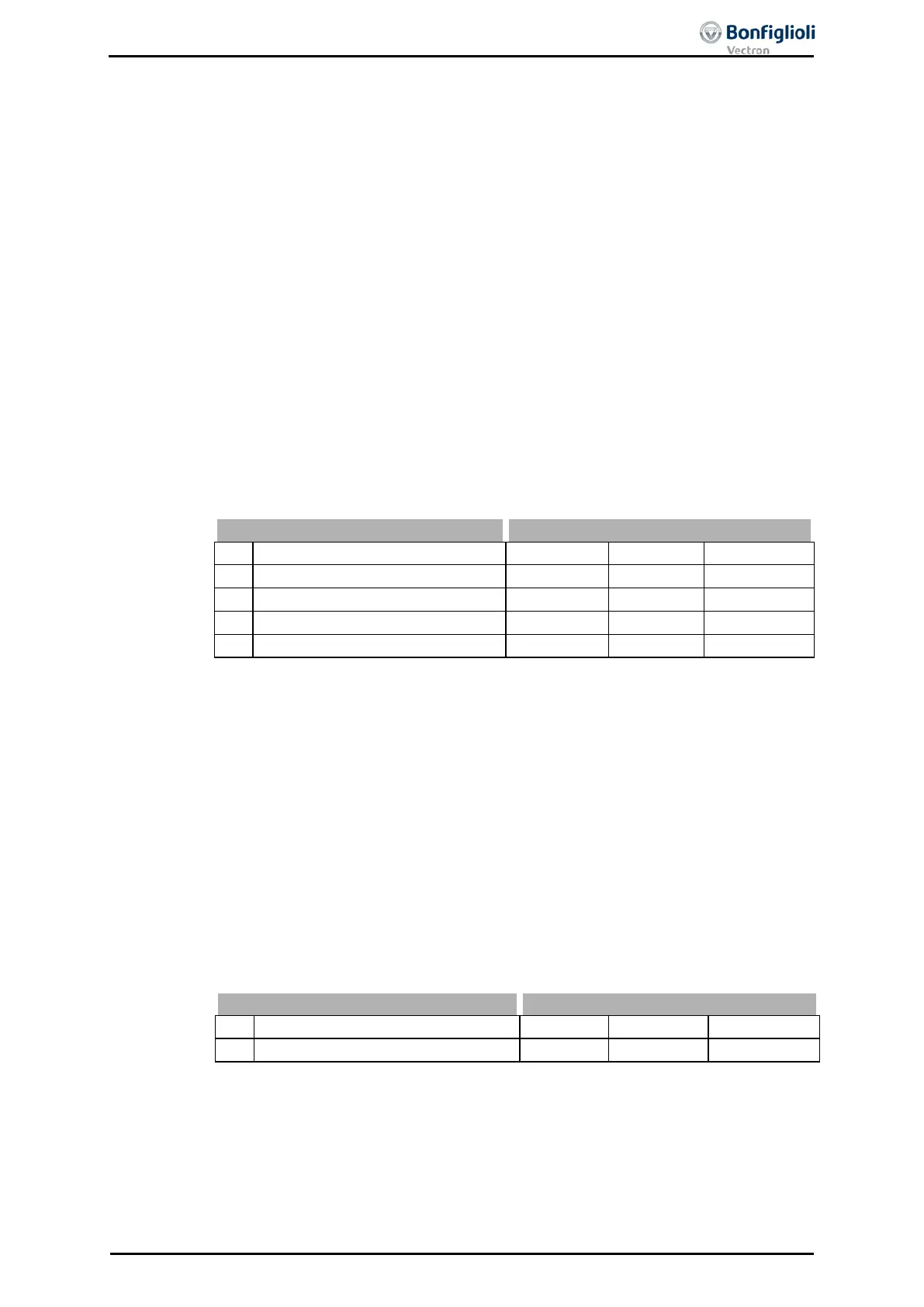
magnetizing characteristic and set the parameters Magnetizing current 50% 713
,
Magnetizing current 80%
714 and
715.
Rated magnetizing current
⋅
⋅
⋅
10.2.4 Rated slip correction factor
The rotor time constant results from the inductivity of the rotor circuit and the rotor
resistance. Due to the temperature-dependence of the rotor resistance and the satu-
ra
tion effects of the iron, the rotor time constant is also dependent on temperature
and current. The load behavior and thus the rated slip depend on the rotor time con-
stant. The guided commissioning determines the machine d
identification and sets the parameter Rated slip correction factor 718
accordingly.
For the fine adjustment or a check of the rotor time constant, proceed as follows:
Load the machine at fifty percent of the Rated frequency 375
. As a result, the voltage
must be approximately fifty percent of the Rated voltage 370, with a maximum toler-
ance of 5 %. If this is not the case, the correction factor must be changed according-
ly. The larger the correction factor is set, the stronger the voltage drop when the ma-
chine is loaded. The value calculated by the rotor time constants can be read out via
the actual value Current rotor time constant 227
. The adjustment should be done at
a winding temperature which is also reached during normal operation of the motor.
718 Rated slip correction factor 0.01 % 300.00 % 100.00 %
06/13 Operating Instructions ACU 125
 Loading...
