12.2 Stopping Behavior
The stopping behavior of the three-phase machine can be defined via parameter
Operation mode 630. Via the logic signals or digital inputs for the parameters Start
clockwise
68 and Start anticlockwise 69, stopping is activated. Assign digital inpu
or logic signals to these parameters. Dependent on the setting of Configuration 30
the parameters are preset to digital inputs. By combining the digital input signals or
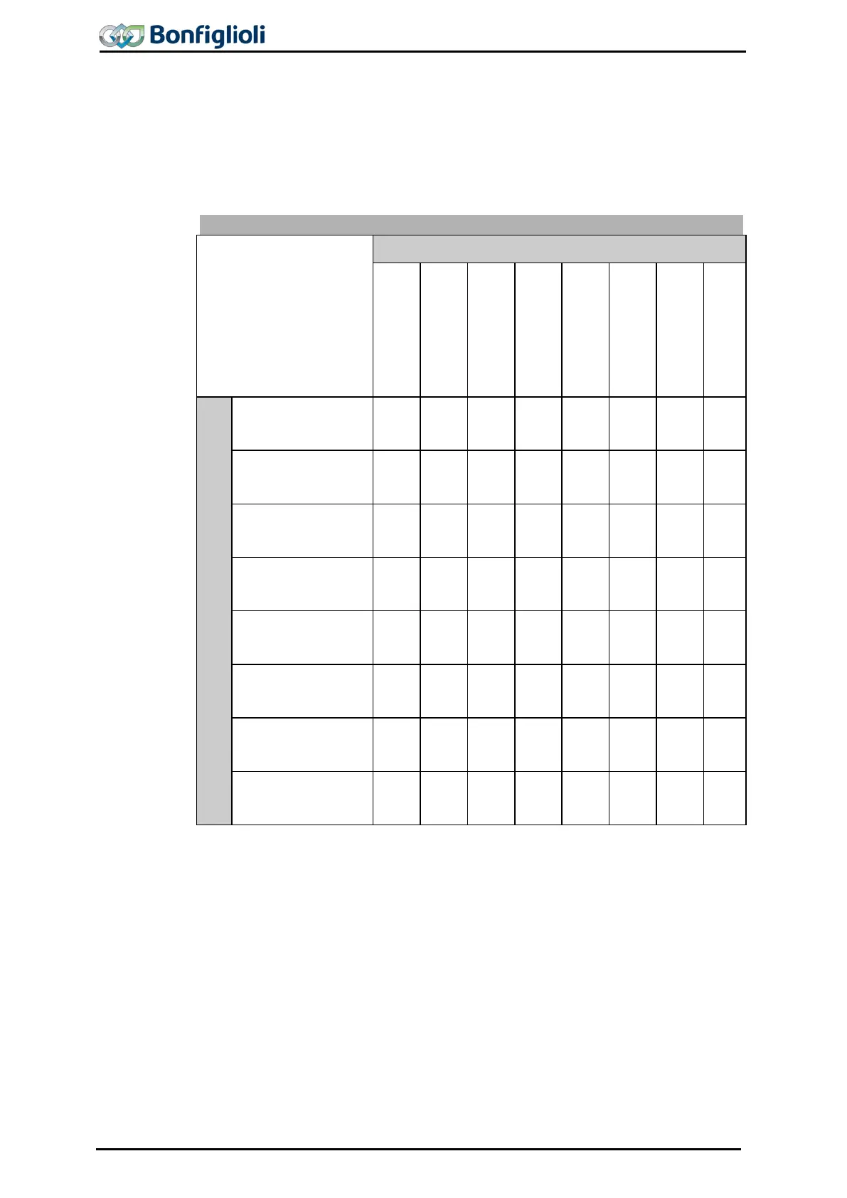
logic signals the stopping behavior can be selected from the following table.
Operation mode 630
Start clockwise = 0 and Start anticlockwise = 0
Stopping behavior 0
Stopping behavior 1
Stopping behavior 2
Stopping behavior 3
Stopping behavior 4
Stopping behavior 5
Stopping behavior 6
Stopping behavior 7
Start clockwise = 1 and Start anticlockwise = 1
Stopping behavior 0
(Free stopping)
0 1 2 3 4 5 6 7
(Stop
10 11 12 13 14 15 16 17
(Stop
20 21 22 23 24 25 26 27
(Stop
and DC brakes)
30 31 32 33 34 35 36 37
(Emergency Stop
40 41 42 43 44 45 46 47
(Emergency Stop
50 51 52 53 54 55 56 57
(Emergency Stop
60 61 62 63 64 65 66 67
Stopping behavior 7
(DC brakes)
70 71 72 73 74 75 76 77
Operation mode 630 of the stopping behavior is to be parameterized according to
the matrix. The selection of the operation modes can vary according to the control
method and the available control inputs.
Example: The machine is to stop according to stopping behavior 2 if the digital logic
signals Start clockwise 68 = 0 and Start anticlockwise 69 = 0.
Additionally, the machine is to stop according to stopping behavior 1 if the digital
logic signals Start clockwise 68 = 1 and Start anticlockwise 69 = 1.
To achieve this, the parameter Operation mode 630 must be set to 12.
By selecting the stopping behavior you also select the control of a mechanical brake if
operation mode „41- Brake release“ is used for one dig
ital output for controlling the
brake.
138 Operating Instructions ACU 06/13
 Loading...
