15.5 Function Modules
15.5.1 Timer
The timer function can be linked to various functions for time-control of digital sig-
nals.
The parameters Operation Mode Timer 1 790 and Operation Mode Timer 2 793 de-
fine the evaluation of the digital input signals and the unit of time of the time func-
0 - Off Signal output is switched off.
1 - Normal, Rising Edge, Sec.
Positive signal edge starts timer (trigger),
time 1 delays the output signal,
time 2 defines the signal period.
2 - Retrigger, Rising Edge, Sec.
Positive signal edge starts timer (trigger),
next positive signal edge within time 1 starts the
delay in time again (Retrigger), time 2 defines
3 -
AND-Connect., Rising Edge,
Sec.
Positive signal edge starts timer (trigger),
if no input signal is received within time 1 the
delay starts again (Retrigger),
if no input signal is received within time 2, the
signal period is terminated.
11 to 13
Operation modes 1...3, negative signal edge
starts timer.
101 to 113 Operation modes 1...3, [in minutes].
201 to 213 Operation modes 1...3, [in hours].
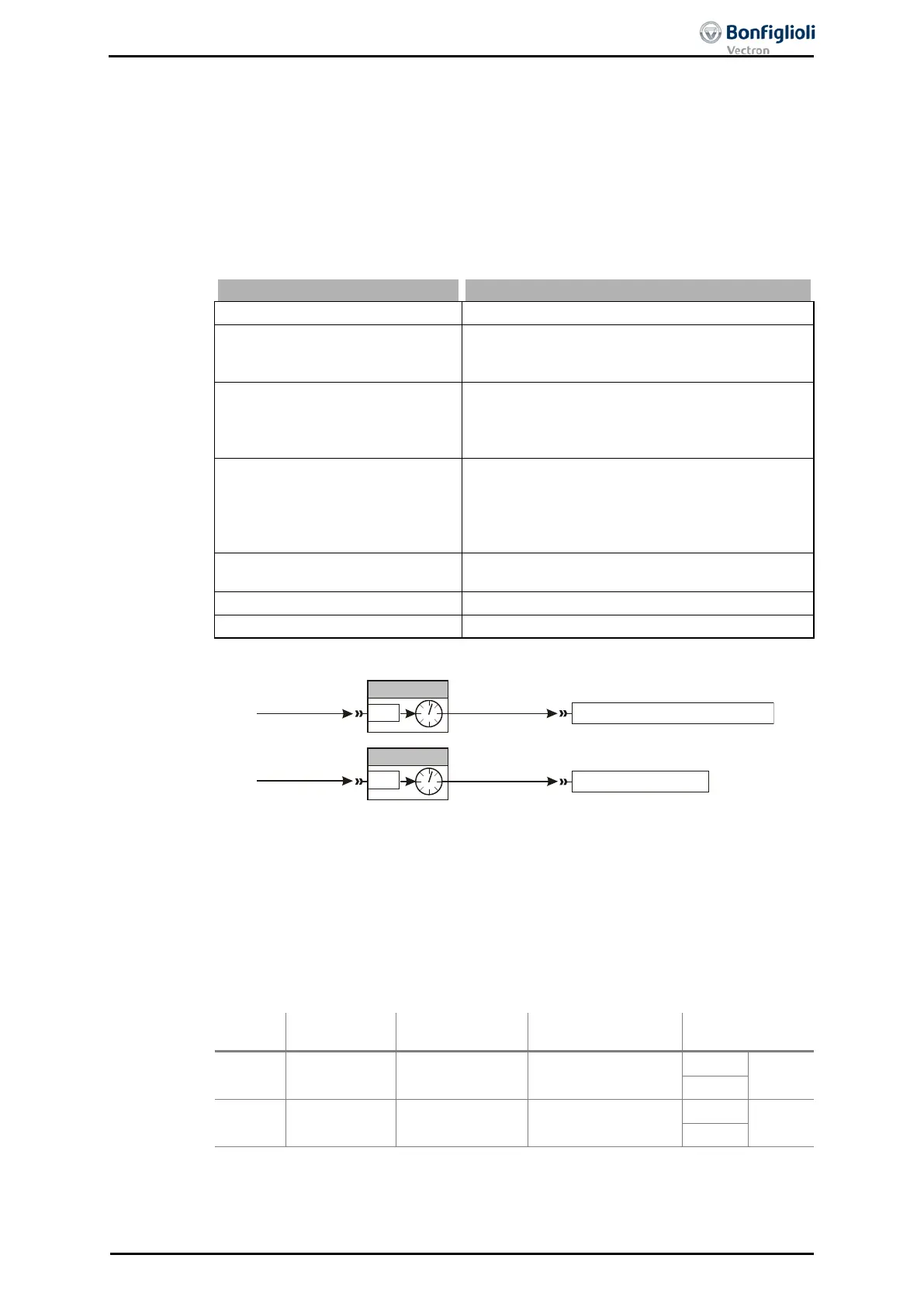
By default, the functions are linked according to the following illustration:
The sources of the digital signals (e.g. 73 - S4IND)
are selected via the parameters
Timer 1 83 and Timer 2 84
. In the factory setting Timer 1 is linked to digital input 4
and Timer 2 is switched off.
The output signal of the timer can be assigned to an inverter function or to a digital
output. By default, Data Set Change-Over 1
is linked to Timer 1 and Timer 2 is not
linked.
The factory setting is Time 2 Timer 1 792 = 0. Signals at digital input
S4IND are transmitted to the Data Set Change Over 1 without time delay.
Parameter for
input signal
Timer 1
Timer 1 83
Operation Mode
Timer 1
790
Time 1 Timer 1 791
Time 2 Timer 1 792
158
-
Timer 1
23
-
Timer 2
Timer 2 84
Operation Mode
Timer 2
793
Time 1 Timer 2 794
Time 2 Timer 2 795
159
-
Timer 2
24
-
1)
For linking with inverter functions
158 - Timer 1
Timer 1 83
P.83
73 - S4IND
7 - Aus
159 - Timer 2
Data Set Change-Over 1 70
Timer 2 84
P.84
No function linked
06/13 Operating Instructions ACU 201
 Loading...
