30
i ABCXY
HDP 100 FAN_
7.4 £ i £ 21.8 105 330 180 424 420
22.8 £ i £ 107.6 82 330 180 424 420
110.6 £ i £ 507.9 58 330 180 424 420
HDP 110 FAN_
8.1 £ i £ 25.0 105 330 180 424 420
24.9 £ i £ 123.4 82 330 180 424 420
120.9 £ i £ 499.4 58 330 180 424 420
HDP 120 FAN_
7.9 £ i £ 25.4 105 345 180 450 450
25.8 £ i £ 125.2 85 345 180 450 450
128.0 £ i £ 523.7 58 345 180 450 450
HDP 130 FAN_
7.3 £ i £ 12.3 130 422 230 540 590
14.1 £ i £ 48.1 105 422 230 540 590
56.5 £ i £ 237.9 82 422 230 540 590
274.5 £ i £ 534.5 58 422 230 540 590
HDP 140 FAN_
8.4 £ i £ 14.4 130 422 230 540 590
16.3 £ i £ 56.2 105 422 230 540 590
65.1 £ i £ 277.5 82 422 230 540 590
315.9 £ i £ 495.3 58 422 230 540 590
HDP 150 FAN_
7.9 £ i £ 14.1 165 472 230 540 665
15.4 £ i £ 38.1 130 472 230 540 665
43.5 £ i £ 77.0 105 472 230 540 665
89.0 £ i £ 303.1 82 472 230 540 665
HDP 160 FAN_
9.0 £ i £ 15.9 165 472 230 540 665
17.5 £ i £ 43.1 130 472 230 540 665
49.4 £ i £ 87.0 105 472 230 540 665
101.1 £ i £ 342.2 82 472 230 540 665
3.6.1.2 - RAFFREDDAMENTO
MEDIANTE SERPENTINA
La serpentina di scambio – opzione SR –
è prevista per essere integrata in un cir-
cuito di raffreddamento la cui realizzazio-
neèacuradell’installatore.
Per una resa ottimale, il circuito di ali-
mentazione, deve corrispondere alle se-
guenti specifiche:
• pressione max 8 bar
• portata min 5 l/min
per HDP 60 … HDP 90
• portata min 10 l/min
per HDP 100 … HDP 140
• temperatura acqua max 20°C
In queste condizioni l’effetto della maggio
-
re capacità di dissipazione termica è rap
-
presentato dal valore di potenza termica
P
TSR
, rilevabile nel capitolo: 4.1
3.6.1.2 - HEAT DISSIPATION
THROUGH COOLING COIL
The cooling coil option SR is designed
for integration in a cooling circuit to be
provided by the installer.
For optimal efficiency the cooling circuit
supply must comply with the following
specifications:
• max. pressure 8 bar
• min flow rate 5 l/min
for HDP 60 … HDP 90
• min flow rate 10 l/min
for HDP 100 … HDP 140
• max. water temperature 20°C
The increased cooling effect obtained in
these conditions is shown by the thermal
capacity value P
TSR
. See the section 4.1
3.6.1.2 - KÜHLUNG MITTELS
KÜHLSCHLANGE
Die Kühlschlange – Option SR – ist für den
Einbau in einen Kühlkreis vorgesehen, der
vom Monteur realisiert werden muss.
Zur Gewährleistung eines optimalen Be-
triebs muss der Versorgungskreis folgen-
de Vorgaben erfüllen:
• Max. Druck 8 bar
• Mindestdurchsatz 5 l/min
für HDP 60 … HDP 90
• Mindestdurchsatz 10 l/min
für HDP 100 … HDP 140
• Wassertemperatur max. 20°C
Die erhöhte Kühlwirkung unter diesen
Bedingungen ist durch den Wert der
Wärmeleistung P
TSR
im Kapitel 4.1 an
-
gegeben.
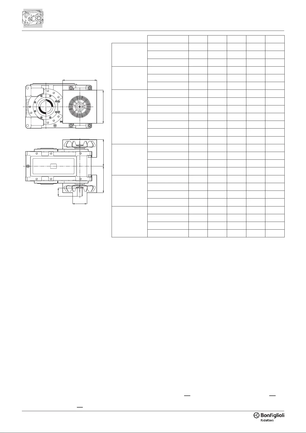
Y
X
B+5B
A
øC
 Loading...