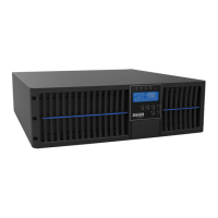
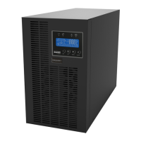
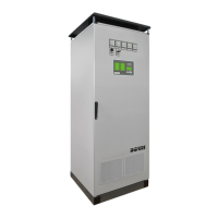
This document serves as the Operating and Maintenance Manual for the BORRI E2001 COMPACT – E3001 COMPACT UPS systems. It covers general descriptions, installation, front panel operation, and troubleshooting.
Function Description:
The UPS (Uninterruptible Power Supply) is designed for commercial and industrial applications, providing continuous, regulated power to a load. It operates as an on-line, double conversion system, meaning the inverter continuously supplies energy to the load, whether mains power is available or not, ensuring battery autonomy. The UPS output is energized even during mains failure, adhering to EN62040-1. The system is designed to provide clean and stable power, immune to micro-interruptions and other disturbances from the mains, thanks to its double conversion topology.
The UPS system comprises several key components:
- Rectifier: Converts AC input voltage into DC voltage to charge the batteries and supply the inverter. The manual describes both 6-pulse and 12-pulse rectifier configurations. A 12-pulse rectifier is used to reduce the distortion of the current absorbed from the mains (THD) to a value <12%. This configuration also uses two 6-pulse rectifier bridges operating with an input voltage having a phase displacement of 30°. For galvanic isolation, a transformer with two secondary windings displaced by 30° (delta/delta-star connection) can be used.
- Battery Charger: Manages the charging of the batteries. The battery charger control logic is integrated into the total-controlled rectifier control board.
- Inverter: Converts DC voltage from the rectifier or batteries back into stable AC voltage for the load. The inverter uses IGBT technology with a frequency commutation of approximately 10 KHz. The control electronics are digital, using a 16-bit µP, which contributes to low distortion and high crest factor currents.
- Static Bypass: Allows the load to be transferred to the mains in case of inverter failure or maintenance.
- Manual Bypass: Provides a means to manually transfer the load directly to the mains for maintenance or serious failure.
Important Technical Specifications:
The manual outlines various settings and parameters for the UPS, accessible via the front panel. These include:
- Input Settings:
- MAX VOLTAGE (Maximum voltage): Sets the percentage of the upper acceptability threshold of the RMS input mains voltage.
- MIN VOLTAGE (Minimum voltage): Sets the percentage of the lower acceptability threshold of the RMS input mains voltage.
- MAX FREQUENCY (Maximum frequency): Sets the percentage of the upper acceptability threshold of the input mains frequency.
- MIN FREQUENCY (Minimum frequency): Sets the percentage of the lower acceptability threshold of the input mains frequency.
- Inverter Settings:
- MIN VDC INPUT (Inverter input minimum voltage): Sets the minimum input voltage of the inverter, below which the inverter will switch off.
- Output Settings:
- MAX VOLTAGE (Maximum voltage): Sets the percentage of the upper acceptability threshold of the RMS output voltage.
- MIN VOLTAGE (Minimum voltage): Sets the percentage of the lower acceptability threshold of the RMS output voltage.
- MAX FREQUENCY (Maximum frequency): Sets the percentage of the upper acceptability threshold of the output frequency.
- MIN FREQUENCY (Minimum frequency): Sets the percentage of the lower acceptability threshold of the output frequency.
- Battery Settings:
- SIZE (Battery dimension): Sets the dimension of the battery (e.g., following replacement).
- HIGH FLOATING (Vmax buffer float charge (A8)): Sets the threshold for alarm A8 (maximum float battery voltage).
- LOW FLOATING (Vmin buffer float charge (A9)): Sets the threshold for alarm A9 (minimum float battery voltage).
- MIN. LEV. 1, 2, 3 (Battery level min 1, 2, 3): Sets thresholds for alarms A16, A17, A18 respectively.
- AUTOM. TEST (Automatic test parameters setting): Enables/disables automatic battery testing, sets the interval (days), and the start time.
- Battery Charger Settings:
- VOLTAGE (Floating charge): Sets the floating charge voltage.
- CURR. LIM. BATT. (Automatic mode max. battery current): Sets the maximum recharge current.
- COMP. TERM. (Thermal compensation): Sets the thermal compensation constant to protect the battery from excess temperatures.
- ENABLE/DISABLE (Enables/disables): Enables or disables boost charge (timed or automatic).
- BOOST MODE (Boost charge mode): Sets the automatic boost charge mode (current or voltage).
- VOLTAGE (Boost charge voltage): Sets the voltage level for boost charge.
- SAFETY TIMER (Boost charge safety timer): Sets the maximum time permitted for the rectifier to remain in boost charge mode.
- FORCED DURATION (Timed boost charge): Sets the duration of timed boost charge.
- DURATION FORCED (Standby time): Sets the boost charge standby time for floating charge.
- CURRENT B. (Boost charge current -> floating charge): Sets the boost charge current threshold at the floating charge.
- CURRENT F. -> B (Floating charge current -> Boost charge): Sets the floating charge current threshold at the boost charge.
- VOLTAGE B. -> F (Boost charge voltage -> floating charge): Sets the boost charge voltage threshold at the floating charge.
- VOLTAGE F. -> B (Floating charge -> Boost charge): Sets the floating charge voltage threshold at the boost charge.
- ENABLE/DISABLE (Enables/disables): Enables/disables manual charge.
- STARTING VOL. (Manual start-up voltage): Sets the manual start-up charge.
- MAX CURRENT (Manual start-up maximum battery current): Sets the manual start-up recharge current.
- SAFETY TIMER (Manual charge timer): Sets the maximum time permitted for the rectifier to remain in manual charge mode.
- DC Voltage Settings:
- MAX VOLT. (Maximum output voltage): Sets the threshold for alarm A5.
- MAX VOLT. DELAY (Max voltage standby time): Sets standby time on alarm A5 activation.
- MIN VOLTAGE (Minimum output voltage): Sets the threshold for alarm A6.
- EMERGENCY LEVEL (Emergency level): Sets the emergency level voltage value.
- ModBus Settings:
- Address: Sets the ModBus slave address (from 1 to 247).
- Transmission speed: Sets the transmission speed of the data on the communication serial port.
- Mode: Sets the parity and number of bits for stoppage on the communication serial port.
- Clock Settings: Allows setting the time and date.
- Firmware Versions: Displays firmware versions for MCU SSW, DSP RAD, and DSP INV.
Usage Features:
The UPS is operated via a front panel with an alphanumeric graphic display (128x64) and 7 function keys.
- Front Panel: Displays device status, measurements, alarms, and allows configuration.
- LEDs: 20 configurable LEDs provide visual indications of the UPS status, such as alternate input mains in tolerance/fault, rectifier OK/not OK, battery OK/flat, inverter OK/not OK, static switch closed/open, output voltage OK/out of tolerance, bypass static switch closed/open, alternate bypass mains in tolerance/fault, manual bypass disabled/enabled, buffer float charge, rapid recharge (Boost), and manual or DC voltage not available from rectifier or battery.
- Function Keys:
- LED TEST: Tests all LEDs.
- Silence buzzer: Silences alarms.
- Back to HOME menu.
- Back to previous menu.
- Scroll menu upwards.
- Scroll menu downwards.
- Select menu/Confirm changes.
- LCD Display: Shows the device name (E2001), status (e.g., UPS RUNNING, INVERTER OFF, RECTIFIER OFF, BYPASS FEEDS LOAD, BYPASS NOT AVAILABLE, INV NOT SYNCHRONISED), and output measurements (Vout, Iout).
- Menu Navigation: The main menus include MEASUREMENTS, COMMANDS, ALARMS, SETTINGS, and INFO.
- Measurements Display: Provides detailed input, rectifier, battery, inverter, bypass, and output measurements (voltage, current, frequency, power, temperature).
- User Commands: Allows actions like RESET UPS, ON/OFF RECTIFIER, ON/OFF INVERTER, BATTERY tests (Request boost, Forced boost, Manual charging, Rapid recharge test, Flat battery rapid test, Flat battery manual test, Flat battery automatic test), and RESUME STARTUP.
- Password Protection: Access to functional parameters is password-protected to prevent unauthorized changes.
- Start-up Procedure: A detailed sequence of steps is provided to safely start the UPS, including closing various switches (RICB, BCB, ICB, SBCB, OCB) and moving selectors (rectifier, inverter).
- Shut-down Procedure: Steps to safely shut down the UPS and disconnect the load.
- Manual Bypass Procedure: Instructions for transferring the load to manual bypass for maintenance.
Maintenance Features:
The manual emphasizes safety rules and provides guidelines for maintenance.
- Safety Rules:
- Only qualified personnel should perform maintenance.
- Dangerous voltage levels are present within the UPS.
- Warning: After UPS shut-down, a dangerous voltage will be present on the battery selector BCB.
- The UPS must be properly earthed.
- Avoid accidents: do not operate the battery charger without the battery connected, never burn the battery (risk of explosion), do not attempt to open the battery (electrolyte is dangerous), and comply with all applicable regulations for battery disposal.
- Product safety: Install a circuit breaker, avoid liquids, do not let foreign bodies penetrate, do not block ventilation grates, and avoid direct sunlight or heat sources.
- Alarms and Troubleshooting: The manual lists numerous alarms (A1-A64) with descriptions, possible causes, and solutions. Examples include:
- A1 MAINS FAULT: Input voltage/frequency out of tolerance. Solutions: Check connections, mains stability, contact support.
- A2 RECTIFIER FUSES BLOWN: Rectifier bridge input fuses fault. Solutions: Contact support.
- A3 RECTIFIER HIGH TEMPERATURE: Rectifier heat sink temperature exceeds threshold. Solutions: Check conduit, fans, cooling system, contact support.
- A4 RECTIFIER OVERLOAD: Rectifier output overload detected. Solutions: Check/reduce load, contact support.
- A5 MAXIMUM RECTIFIER VOLTAGE: Direct voltage surpassed higher threshold. Solutions: Check voltage, reset device, contact support.
- A6 MINIMUM RECTIFIER VOLTAGE: Direct voltage surpassed lower threshold. Solutions: Check voltage, reset device, contact support.
- A7 EMERGENCY LEVEL: Emergency level set at rectifier output voltage. Solutions: Check conditions, contact support.
- A8 MAXIMUM FLOAT BATTERY: Battery voltage on floating charge surpassed higher threshold. Solutions: Check output direct voltage, contact support.
- A9 MINIMUM FLOAT BATTERY: Battery voltage on floating charge surpassed lower threshold. Solutions: Check output direct voltage, contact support.
- A10 SAFETY TIMER: Maximum time expired for manual or rapid charge. Solutions: Check battery status, reset device, contact support.
- A12 RICB OPEN: Input switch is open. Solutions: Check switch auxiliary contact, contact support.
- A13 BCB OPEN: Battery switch is open. Solutions: Check switch auxiliary contact, contact support.
- A14 ROCB OPEN: Rectifier output switch is open. Solutions: Check switch auxiliary contact, contact support.
- A15 FLAT BATTERY: Battery is flat. Solutions: Check alarms, execute procedures, contact support.
- A16-A18 MIN BATTERY LEVEL 1, 2, 3: Battery reaches minimum levels. Solutions: Check battery voltage, alarms, procedures, contact support.
- A19 EPO PRESSED: EPO button pressed. Solutions: Check emergency button auxiliary contact, contact support.
- A20 RECTIFIER THERMAL IMAGE: Thermal image activated due to prolonged overload. Solutions: Check/reduce load, contact support.
- A21 MANUAL INTERRUPTED: Manual charge shut-off. Solutions: Check alarms, procedures, contact support.
- A22 BATTERY REVERSE POLARITY: Inverse polarity detected on battery terminals. Solutions: Check battery connection, contact support.
- A23 BATTERY TEST FAILED: Battery test not passed. Solutions: Check battery status, contact support.
- A24 Q11 OPEN: Switch Q11 open. Solutions: Check switch auxiliary contact, contact support.
- A25 RECTIFIER CAN ERROR: Rectifier parallel CAN-BUS serial communication not working. Solutions: Check settings, CAN-BUS cable, contact support.
- A26 RECTIFIER PARALLEL FAULT: System cannot manage to sub-divide load. Solutions: Check current sensor, parallel switch contacts, contact support.
- A28 SBCB OPEN: SBCB bypass switch open. Solutions: Check switch auxiliary contact, contact support.
- A29 ELCB OPEN: ELCB emergency line switch open. Solutions: Check switch auxiliary contact, contact support.
- A30 RECTIFIER OFF BY USER: Rectifier manually switched off. Solutions: Check "Possible causes", contact support.
- A31 RECTIFIER CONTROL ERROR LOOP: Circuit fault of control or measurement. Solutions: Check connections, contact support.
- A33 DISCONNECTED PROBE: Temperature probe disconnected. Solutions: Check probe connection, contact support.
- A34 INVERTER OFF BY USER: Inverter manually switched off. Solutions: Check "Possible causes", contact support.
- A35 INVERTER INPUT VOLTAGE NOT OK: DC voltage inbound of inverter out of tolerance. Solutions: Check "Possible causes", contact support.
- A36 INVERTER HIGH TEMPERATURE: Inverter heat sink temperature exceeds threshold. Solutions: Check conduit, fans, cooling system, contact support.
- A37 INVERTER OVERLOAD: Inverter output overload detected. Solutions: Check/reduce load, contact support.
- A38 ICB OPEN: Inverter input switch ICB open. Solutions: Check switch auxiliary contact, contact support.
- A39 OCB OPEN: OCB output switch open. Solutions: Check switch auxiliary contact, contact support.
- A40 EXTERNAL OCB OPEN: External output switch open. Solutions: Check switch auxiliary contact, contact support.
- A41 MBCB CLOSED: Manual bypass switch MBCB closed. Solutions: Check switch auxiliary contact, contact support.
- A42 INVERTER OUT OF TOLERANCE: Inverter output voltage out of tolerance. Solutions: Switch inverter on, contact support.
- A43 SHORT CIRCUIT: Inverter output short circuit. Solutions: Eliminate short circuit, contact support.
- A44 INVERTER THERMAL IMAGE: Thermal image activated due to prolonged overload. Solutions: Check/reduce load, contact support.
- A45 BYPASS NOT OK: Bypass not available or voltage/frequency out of tolerance. Solutions: Check bypass voltage parameters, contact support.
- A46 BYPASS FEEDS LOAD: Bypass feeds the load. Solutions: Switch inverter on, contact support.
- A47 BYPASS SWITCH: Bypass/normal switch is in bypass position. Solutions: Move bypass switch, check auxiliary contact, contact support.
- A48 RE-TRANSFER BLOCKED: UPS blocked under bypass. Solutions: Reset/check static operation, contact support.
- A49 MINIMUM OUTPUT VOLTAGE: Output voltage below minimum tolerance. Solutions: Switch inverter on, contact support.
- A50 MAXIMUM OUTPUT VOLTAGE: Output voltage over maximum tolerance. Solutions: Contact support.
- A51 INVERTER FEEDS LOAD: Inverter feeds the load (OFF-LINE configurations only). Solutions: Move bypass switch, check auxiliary contact, contact support.
- A52 FANS FAIL: At least one fan not working correctly. Solutions: Check fan power supply, replace fan, contact support.
- A53 INVERTER CAN ERROR: Inverter parallel CAN-BUS serial communication not working. Solutions: Check settings, cable, contact support.
- A54 CAN INVERTER DISCONNECTED: Inverter parallel cable not connected. Solutions: Check cable, contact support.
- A55 LOST REDUNDANCY: Parallel inverter number insufficient for minimum redundancy. Solutions: Reset/turn off systems, contact support.
- A61 INTERNAL ERROR: Error occurred inside control logic. Solutions: Contact support.
- A62 START SEQUENCE BLOCKED: Start sequence blocked due to error. Solutions: Contact support.
- A63 EEPROM ERROR: Control unit detected EEPROM parameter error. Solutions: Contact support.
- A64 COMMON ALARM: At least one alarm from UPS logic. Solutions: Check alarms, execute procedures.
- Event Log: The Log page displays machine events with event code, description, date, time, and position in the log (up to 500 events). Events are displayed in increasing order of numerical code, are visible until present, and are automatically saved.
- Receipt of the UPS: Instructions for inspecting the UPS upon arrival and reporting any damage to the transport company.
- Handling of the UPS: Guidelines for moving the UPS using a wood pallet, pallet truck, or forklift.
- Positioning and Installation: Requirements for a clean, dry, and adequately cooled room for installation.
- Electrical Connection: Emphasizes that electrical connection is part of the work normally provided by the supplier and that the UPS manufacturer is not responsible for the electrical installation. It also highlights the need for a main circuit breaker at the front of the UPS.
- Battery Installation: Provides important safety information regarding battery installation, including prescriptions of EN62040-1, temperature limits (0-25°C for optimal life, up to 40°C for reduced life), and the risk of explosive hydrogen and oxygen mixture. It is recommended to install batteries when the UPS is capable of charging them.