Adjustments
Miter Scale (Vernier) indicator
Adjustment
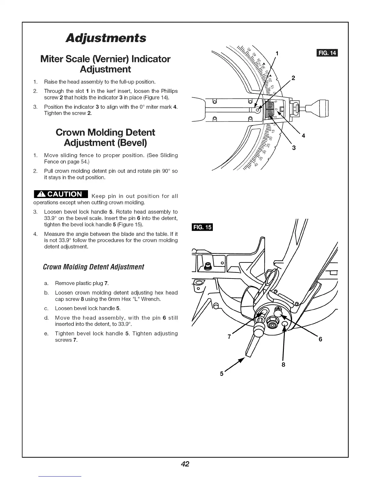
1. Raise the head assembly to the full-up position.
2. Through the slot 1 in the kerf insert, loosen the Phillips
screw 2 that holds the indicator 3 in place (Figure 14).
3.
Position the indicator 3 to align with the 0° miter mark 4.
Tighten the screw 2.
Crown Molding Detent
Adjustment (Bevel}
1. Move sliding fence to proper position. (See Sliding
Fence on page 54.)
2. Pull crown molding detent pin out and rotate pin 90° so
it stays in the out position.
r !_[e_*--_ill|[e]_m Keep pin in out position for all
operations except when cutting crown molding.
3. Loosen bevel lock handle 5. Rotate head assembly to
33.9 ° on the bevel scale. Insert the pin 6 into the detent,
tighten the bevel lock handle 5 (Figure 15).
4. Measure the angle between the blade and the table. If it
is not 33.9 ° follow the procedures for the crown molding
detent adjustment.
CrownMoldingDetentAdjustment
a. Remove plastic plug 7.
b. Loosen crown molding detent adjusting hex head
cap screw 8 using the 6mm Hex "L" Wrench.
c. Loosen bevel lock handle 5.
d. Move the head assembly, with the pin 6 still
inserted into the detent, to 33.9 °.
e. Tighten bevel lock handle 5. Tighten adjusting
screws 7.
3
6
8
42