Unit Installation
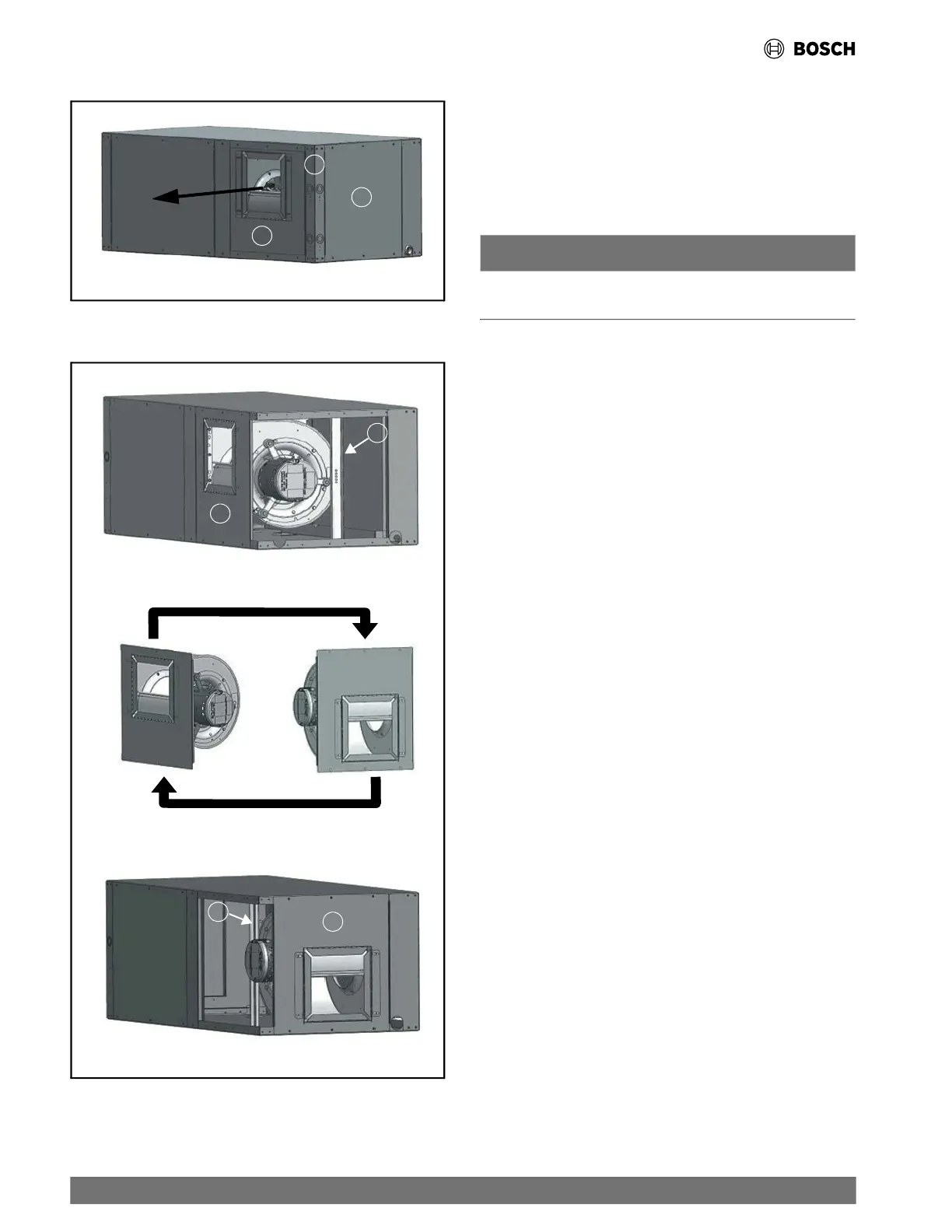
Fig. 4 Straight-Through Orientation
A
C
B
Fig. 5 Blower Configuration
D
B
B
D
STRAIGHT
THROUGH
END
BLOW
To convert the supply air direction, follow the steps below:
(See Fig. 3, Fig. 4, and Fig. 5.)
1. If the unit is connected to power, shut OFF the unit and
disconnect switch or circuit breaker.
2. Locate the Motor Access Panel (A). Remove the three
screws at top and the three screws at the bottom of the
panel. Remove the access panel and place it aside.
NOTICE
Be careful not to damage the refrigerant coils or any other
internal unit components.
3. Locate Blower Panel (B). Remove the three screws from top
and the three screws from bottom of the panel. Leave the
blower panel in place on the base pan.
4. Locate Access Panel Corner Post (C). Remove the four
screws from top and the four screws from the bottom.
Remove the corner post and set it aside.
5. Locate Blower Support Bracket (D). Remove the one screw
and set it aside.
6. Move Blower Panel (B) with blower to desired location,
rotating it 180°. (See Fig. 5.) The motor power and
control harness can be unplugged to facilitate blower
relocation.
7. Reinstall Access Panel Corner Post (C) using the eight
screws previously removed.
8. Fasten Blower Panel (B) using the six screws previously
removed.
9. Reinstall and fasten Blower Support Bracket (D) using the
one screw previously removed.
10. Reattach the motor power and control harness if
disconnected earlier.
11. Reinstall and fasten Motor Access Panel (A) using the six
screws previously removed.
5.5.2 Mounting Horizontal (HZ) Units
While HZ units may be installed on any level surface strong
e
nough to
hold their weight, they are typically suspended above
a ceiling by threaded rods. Attach the unit corners using a
hanging bracket kit supplied with the HZ units. The rods must be
securely anchored to the ceiling. Refer to the hanging bracket
assembly and installation instructions for details.
14 |
CL Series Heat Pumps — 8733838716 (2024/05)

 Loading...