Unit Installation
NOTICE
To prevent voltage drops in the control circuit, do not exceed
the recommended thermostat wire lengths detailed in
Table 6.
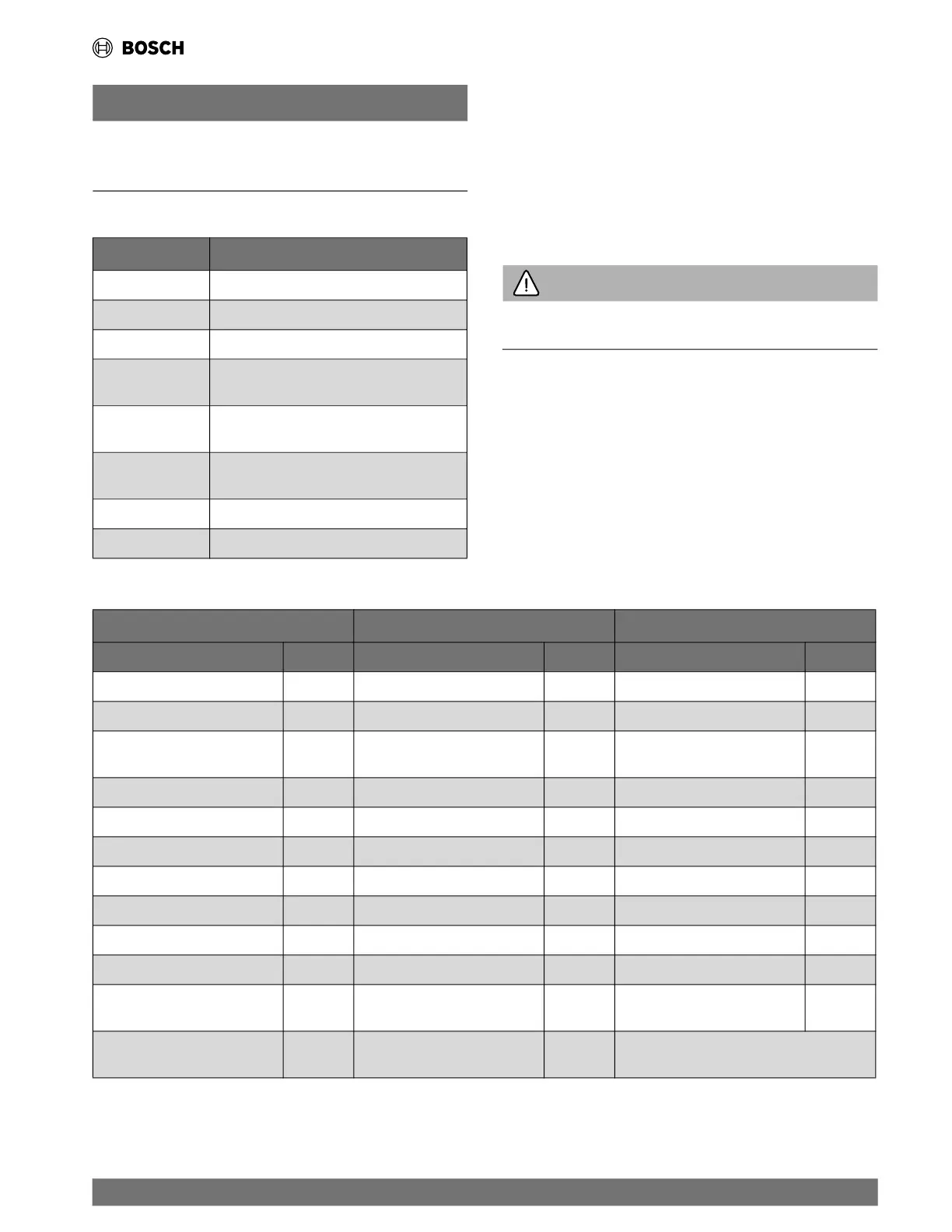
Table 4 Unit Thermostat Connections
Connection Function
Y1 First-Stage Compressor Operation
G Fan
O Reversing Valve (energized in cooling)
W1
Auxiliary Electric Heat (runs in conjunction with
compressor)
NC
Transformer 24 VAC Common (extra
connection)
C1
Transformer 24 VAC Common (primary
connection)
R Transformer 24 VAC Hot
H Dehumidification Mode
5.10.2 VA Capacity
The VA capacity of the transformer must be considered when
connecting low
-voltage accessories to the heat pump such as
thermostats or solenoid valves. Table 5 shows the VA draw of
factory-mounted components in the low-voltage heat pump. The
total VA draw of th
e heat pump internal components plus
attached accessories must be lower than the VA capacity of the
unit control transformer.
WARNING
Exceeding the transformer capacity will result in low control
voltage, erratic unit operation, or damage to the heat pump.
Table 5 Low-Voltage VA Draw —Standard Construction, Hot Gas Reheat or Economizer, and Optional Components
Standard Construction Optional Components Optional Components
Component VA Component VA Component VA
Blower Relay (PSC motors only) 10 Total VA Draw from “Standard” 37 Compressor Monitor Relay 4
Reversing Valve Solenoid 12 Option Card 5 Blower Monitor Relay 4
Compressor Contactor Single
Phase
10 Hot Gas Reheat Solenoid 9 Energy Management Relay 4
UPM Board 5 Economizer Valve 3 Fire Alarm Relay 4
Heater Relay 10
Aux Relay 10
Heating/Blower Relay 4
5600 DDC 26
EON Board 1
Leaving Water Valve 7
Compressor Contactor
Three Phase
10
Total VA Draw 37 Total VA Draw 54
Total Draw is Dependent on
the Options Installed
| 21
CL Series Heat Pumps — 8733838716 (2024/05)

 Loading...