36
Bevel Cuts
A “bevel cut” is a cross-cut made with the blade
perpendicular to the fence and with the table set
a
t 0° miter. The blade can be tilted at any angle
within the saw’s range: 47° left and -2° right from
the vertical.
T
he bevel scale is sized and positioned for easy
reading. And the side bevel lock lever is to lock and
unlock the various settings.
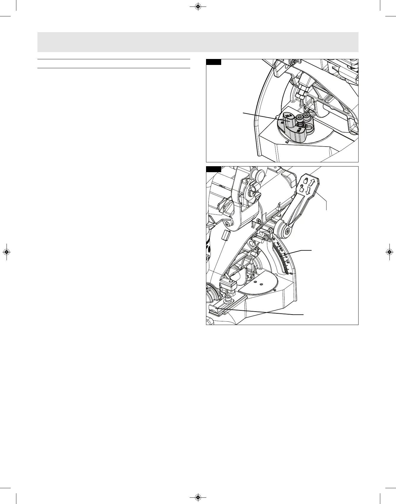
A rotating Left Bevel Stop indicator allows you to
set the most common bevel stops 0°, 22.5°, 33.9°,
45° and 47° Left, (figure 41). The 33.9° bevel stop
is for cutting 38° “spring angle” crown molding flat
on the table. (See Compound Cuts for more
information.)
A -2° Right Bevel Stop is also available for back
cutting applications. Simply slide this stop forward
and back to engage the 0° stop and disengage for
-2° stop. (see figure 42)
SETTING THE SAW TO MAKE A BEVEL CUT
1. Extend the left base extension and left sliding
fence (See “Sliding Fence and Base Extension”
on pages 30 and 31)
Note: Be sure to move left sliding fence away
from the blade to avoid cutting into the fence
when bevel cutting. The left sliding fence may
need to be removed when performing extreme
bevel cuts and most compound cuts (see page
30).
2. With one hand, pull the bevel lock lever forward
to unlock the saw head. (see figure 42)
3. Adjust your left bevel stop to one of the three
pre-set locations 22.5°, 33.9°, 45° and 47° Left, if
desired, tilt head left until you reach the desired
angle on your bevel scale. (see figure 42)
4. Lock the bevel lock by pushing it toward the back
of the saw.
5. Follow procedures for either chop cut or slide cut
(see page 33).
Bevel Scale
-2
° Bevel
Stop
FIG. 42
Bevel Lock
Level
Bevel Stop
Indicator
FIG. 41
Saw Operations