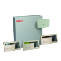
D6412/D4412 Operation and Installation Guide
D6412/D4412
Page 21© 2003 Bosch Security Systems 45349E
5.0 Power Outputs
5.1 Circuit Protection
Three self-resetting thermal circuit breakers protect the panel from short circuits on both the continuous and programmable
power outputs. If the panel is programmed for power supervision and a short is sustained on one of the power outputs, the
panel transmits a Battery Low or Battery Missing Report.
One breaker protects Auxiliary Power and the Installer’s Keypad Connector; a short on one disrupts power to the other.
One breaker protects the Alarm Power Output (Alrm + Terminal) and one breaker protects the battery.
5.2 Available Power
5.2.1 Auxiliary Power
Use the auxiliary power terminals to power devices requiring continuous power. See Section 14.0 Installation Label and
Section 15.0 Terminal Quick Reference for the location and description of these terminals.
5.2.2 Installer’s Keypad Connector
Use this connector to connect an installer’s keypad to the panel for programming and diagnostics.
5.2.3 Alarm Power
Provides positive 12 VDC for Programmable Output 2 (PO2 ) when it is configured as a siren driver and Programmable
Output 1 (PO1) when it is configured as the alarm output.
5.3 Continuous Power Output
5.3.1 Continuous Current Draw
The continuous current draw for powered devices connected to the Aux Power terminals, Installer’s Keypad Connector, and
Outputs PO1 to Programmable Output 4 (PO4 ), when programmed for continuous output, are restricted as follows:
• 120 mA for Fire and Combined Fire/Burglary systems
• 400 mA for UL Burglary systems
• 600 mA for other applications (not investigated by UL)
5.4 Alarm Power
5.4.1 Available Power
The system combines the 600 mA of primary power produced by the power supply with the secondary power source (the
battery) to produce a total of 1.5 A of alarm power at 11.5 VDC to 12.4 VDC. Alarm power is available at the Alrm +
terminal. The panel uses PO1 through PO4 to activate Alarm power (see Section 5.5 Output Programming).
MPORTAN
Fire systems are prohibited from using the battery for determining alarm power. Use the Fire System Power
Formula below to calculate the current available for fire and combined fire/burglary systems.
Fire System Power Formula
To calculate the current available at the Alrm + terminal for fire and combined fire/burglary systems:
1. Add together the current draws for all devices connected to the Aux terminals and the Installer’s Keypad
Connector. This total is the total current required for the Normal Standby Condition (NSC).
2. The current available for NSC is 600 mA. Subtract the NSC current required calculated in Step 1 from the
NSC current available, 600 mA. The difference is the Alarm Current available the Alrm + terminal
(480 mA maximum).
Formula format: 600 mA – NSC current required (Step 1) = Alarm Current available (480 mA maximum)
Refer to A-4: Current Rating Chart for Standby Battery Calculations for module/accessory current requirements.
Power Outputs

 Loading...