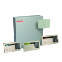
D6412/D4412 Operation and Installation Guide
D6412/D4412
Page 51© 2003 Bosch Security Systems 45349E
SDI Devices
12.3.2 DX4010 to D6412/D4412 SDI Bus Wiring Connections
See Figure 38 for acceptable power wiring connections. See Section 4.3 for external power supply restrictions.
Y
G
B
R
D6412/D4412
X4010 to D6412/D4412 Power Connections
DX4010
Red (+)
Black (-)
Yellow
Green
External 12 VDC
Power Supply
(+) (-)
Y
G
B
R
D6412/D4412
DX4010 to External Power Supply Connections
Black (-)
Yellow
Green
DX4010
Red (+)
Figure 38: DX4010 Power Connections
12.3.3 RAM IV Direct Connection
The DX4010 can be used to connect directly to the panel for RAM IV remote programming. It also lets the user perform
diagnostic and history retrievals in RAM IV.
To connect directly to the panel for a RAM IV session:
1. Make sure the DX4010’s Address DIP Switches are set to Address 0. See the DX4010 Installation Guide
(P/N: 49539) for address DIP Switch location and positioning.
2. Using a null modem cable (not included), connect the DX4010 to COM port 1 or 2 (or an available COM
port) on your computer. The DX4010 has a DB-9 male serial connector. If this does not fit your computer,
you need an adapter.
3. Wire the flying leads of the colored cable connector (included with panel) to the DX4010’s SDI Bus
terminals. Plug the connector end onto the D6412/D4412. See Figure 39 for details.
4. Plug the connector end of the cable onto the panel PCB. See Figure 40 for details.
Serial Port
Com Port
DX4010
Null Modem Cable
D6412/D4412
R
Y
G
B
JP2
Sel
AUX/Data
Connector Pin
Location
DX4010 SDI Bus
Black (GND)
Green
Yellow
Red
Figure 39: Creating a RAM IV Direct Connection

 Loading...