D6600 | Operation and Installation Guide | Contents
4 Bosch Security Systems | 2/05 | 4998122704E
Figures
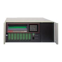
Figure 1: D6600 Communications
Receiver/Gateway (front view)..................7
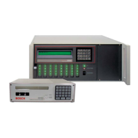
Figure 2: D6600 Communications
Receiver/Gateway (rear view) ...................8
Figure 3: Receiver Card Placement...........................8
Figure 4: D6640/D6641 Line Card ...........................9
Figure 5: D6645 Line Terminator Card....................9
Figure 6: D6640/D6641 LED Descriptions..............9
Figure 7: Removing the top cover of the D6600 ...10
Figure 8: Inserting the D6645 Line Terminator
Card ............................................................10
Figure 9: Securing the D6645 Line Terminator
Card ............................................................10
Figure 10: D6615 CPU Terminator Card.................11
Figure 11: Location of D6600 Battery Connector....12
Figure 12: D6600 Back Panel Showing Input/
Output Ports...............................................15
Figure 13: Input Wiring for Reverse
Configuration.............................................15
Figure 14: D6600 NetCom System Connection
Diagram - C900TTL-E and Any Control
Panel ...........................................................24
Figure 15: D6600 NetCom System Connection
Diagram - D9133TTL-E and Bosch
Control Panels ...........................................25
Figure 16: NO DATA RECEIVED Message...........25
Figure 17: D6600 System – Direct Connect.............26
Figure 18: D6600 System – Standard/Network
Automation ................................................26
Tables
Table 1: D6600 Supported Communication
Formats ........................................................ 5
Table 2: Battery Supervision..................................... 7
Table 3: System Trouble ........................................... 7
Table 4: D6600 Line Cards and Modules............... 7
Table 5: Battery Voltage Display ........................... 14
Table 6: Calculating Standby Capacity Required
by UL ......................................................... 14
Table 7: Minimum Standby Battery Chart ........... 14
Table 8: Terminator Card Configuration.............. 16
Table 9: Testing Communication Links................ 21
Table 10: Hardware Troubleshooting Guide.......... 28
Table 11: D6600 Specifications ................................ 31