D6600 | Operation and Installation Guide | 4.0 D6600 Specific Cards
.
Bosch Security Systems | 2/05 | 4998122704E 9
4.0 D6600 Specific Cards
4.1 D6640/D6641 Line Cards and D6645
Line Terminator Card
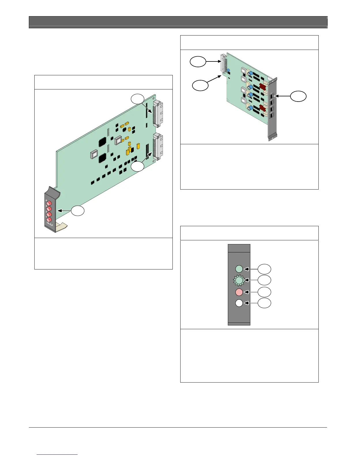
Figure 4: D6640/D6641 Line Card
1
2
3
1 - 48-pin connection to D6645 Line Termination
Card
2 - 40-pin connection to D6600 Back Plate
3 - LEDs (refer to Figure 6)
Figure 5: D6645 Line Terminator Card
1
3
2
1 - 48-pin connection to D6640/D6641 Line Card
2 - Alignment Guide - Stabilizes the connection
and acts as a guide for connecting the
terminator card to the line card.
3 - Telco Line Jacks - Standard telephone lines
connect to the RJ11C jacks.
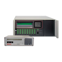
4.1.1 D6640/D6641 LED Descriptions
The LED is active until the system acknowledges the
entire transmission and the telephone line is ready to
receive signals
Figure 6: D6640/D6641 LED Descriptions
OL/LF
1
2
3
4
1
2
3
4
1 - Flashes green when an incoming call rings.
2 - Glows green when the receiver is online with
an incoming call.
3 - Glows red when the line card detects a line
fault condition.
4 - LED is off and ready to receive signals or is
disabled in the software.