6720220327
Revised 11-11 Subject to change without prior notice
Closet Installation
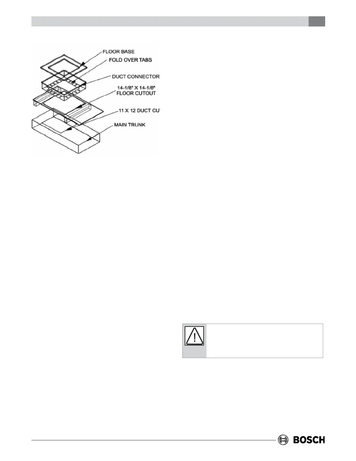
Prior to installing the furnace make sure the holes
are cut into the oor for the refrigerant tubing, the
drain line, the electrical wiring, the thermostat
wiring and the condenser control wiring.
1. Remove the top shipping cover and corner
posts.
2. Remove the bottom shipping cover.
3. Remove the blower and control box access
panel (door).
4. Remove the coil compartment access panel
(door).
5. Place the unit into position using one of the
following choices:
A. If the Combustible Floor Base is used you
slide the unit on to the combustible oor
base until the unit is touching the anges on
the back of the oor base.
B. If the Combustible Floor Base is not used
you slide the unit over the duct opening until
the opening in the unit lines up with the duct
opening in the oor.
6. Secure the unit by one of the two choices:
A. If the Combustible Floor Base is used you
secure the furnace to the oor by drilling two
holes through the furnace base and the oor
base at the right and left front inside corners
of the cabinet. Use two screws to secure the
furnace to the oor.
B. If the Combustible Floor Base is not used
you secure the unit to the oor by drilling
two holes through the furnace base at the
left and right front inside corners of the
cabinet. Use two screws to secure the unit to
the oor.
7. Use caulking, sealers, and/or tape to seal
between the combustible oor base and the
opening on the unit or between the opening on
the unit and the duct in the oor.
8. Connect the electrical supply wires and the
thermostat control wires in the control box.
9. Connect the refrigerant lines to the coil.
10. Re-install the coil compartment access panel
(door) and secure with the screws that were
removed in Step 3.
11. Re-install the blower and control box access
panel (door) and secure with the screws that
were removed in Step 2
12. Turn the power on to the unit by following the
procedure in the Users Information Manual.
13. Set the thermostat to the desired temperature.
Refer to the unit nameplate for specic electrical
data.
Disconnectpoweratmainfuseorcircuitbreaker
distributionpanelbeforewiringunittoprevent
shockorrehazard.
The unit internal wiring is complete except for the
power supply and the thermostat wires. The use of
cable connectors on incoming power supply wires
to relieve any strain on wiring is recommended.