Subject to change without prior notice Revised 11-11
6720220327
3. Vent air from the water tank by opening a hot
water spigot.
4. Vent and ush the supply and return lines by
attaching a hose to the volume purge valve and
running purge water to a safe location. Run
approximately 5 gallons of water at a high ow
rate to purge.
5. Energize the unit by switching on the line voltage
source and the thermostat. The fan and pump
should start simultaneously. The water coil
should become warm after a few minutes of
operation.
6. Units are rated at temperatures up to 180°F. Set
water source temperature at design temperature
and take proper safeguards for water usage at
supply points as per local codes and safety
considerations.
Heatpumpcondensingsectionsarenotcableof
producing180°Fwater.Thismustcomefroma
boilersource.ContactBoschforratingsand
capacitiesforboilersystemuse.
For short periods of time during freezing
temperatures if the system is to be left unused, to
prevent freezing of the air handler and piping, do the
following:
1. Do not turn the system off; leave the thermostat
to the air handler left on the heat setting to
maintain a space temperature above freezing
conditions.
2. If the water heater and/or air handler must be
shut down for extended periods, a qualied
service technician should insure that the air
handler and coil are completely drained of water.
The lter must be changed monthly to permit proper
airow for safe and efcient operation. All other
maintenance should be performed by a licensed
technician.
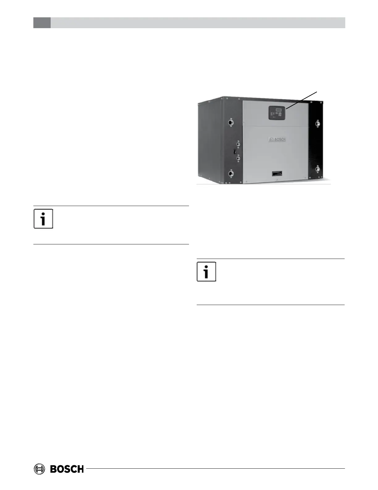
In order to allow your room thermostat or DDC
controller to control the operation mode (cooling
or heating) that your water-to-water unit is
running, you will need to purchase the DY AUTO
CHANGEOVER CONTROLLER
(Bosch Part #:7 738 000 397).
ThisaccessoryisonlyneededforaHYair
handlerwithapairedwater-to-waterunitwitha
unitmountedcontroller.Ifyourwater-to-water
unitisremotecontrolled,itisalreadysetupto
functioncorrectlywithanHYairhandler.
This controller will convert an AC signal from the
thermostat or DDC controller when a call for
cooling or heating is made based upon the set
point to a resistance value that the unit mounted
controller will interpret as a water temperature.
This will cause the water-to-water unit to go into
cooling or heating mode as dictated by the
thermostat or DDC controller call.
Connect the “S2” connections on the back of the
water-to-water unit mounted controller to the “S2”
connections on the Auto Changeover Controller. If
a thermostat will be used to control the air
handler, then route a wire from the “O” connection
and from the “C” connection from the back of the