6720220327
Revised 11-11 Subject to change without prior notice
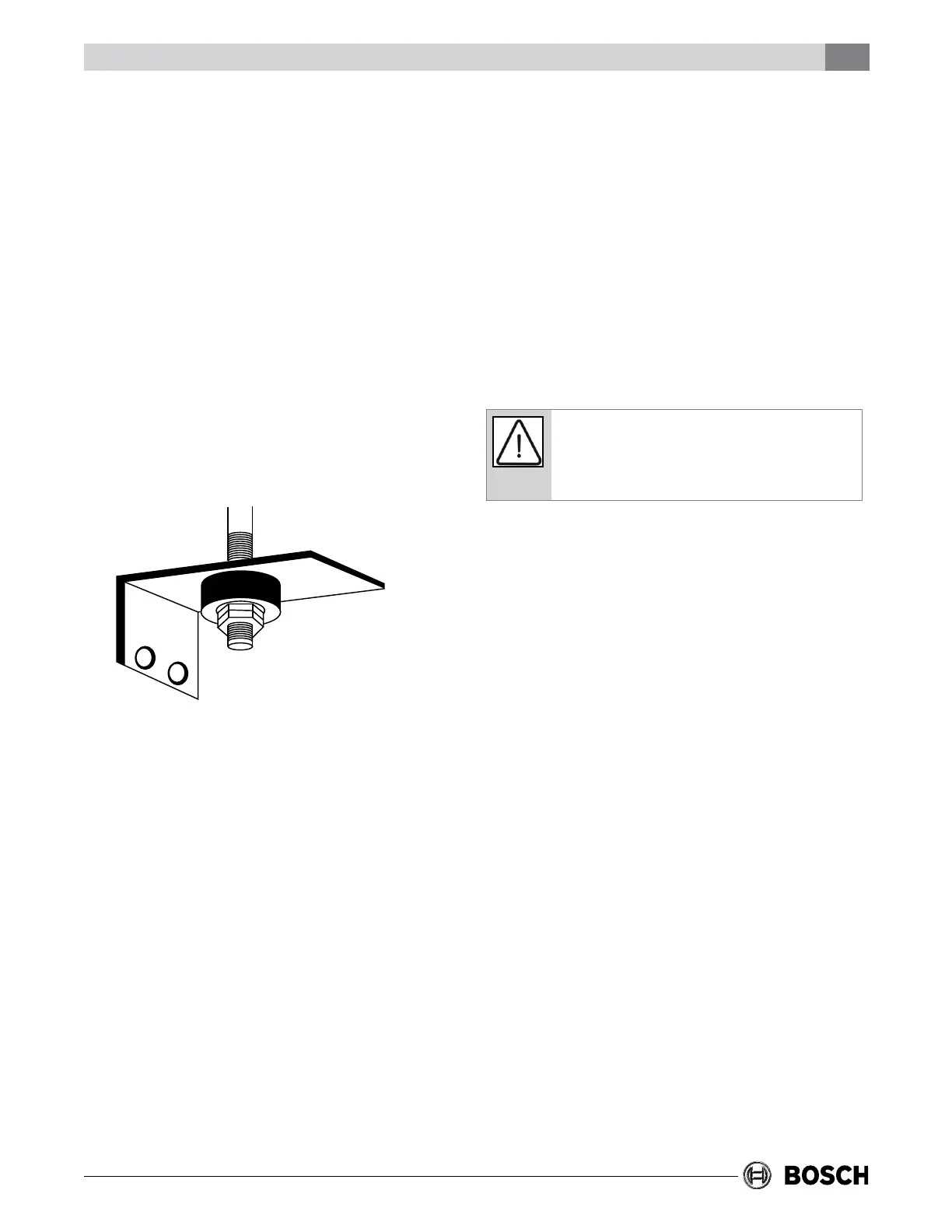
While horizontal units may be installed on any level
surface strong enough to hold their weight, they are
typically suspended above a ceiling by threaded
rods and a unistrut framing system; however
hanging bracket kits (See Figure 1) are available
from Bosch as an accessory (Part # 930-004 or
930-006). If the hanging bracket kit is purchased
from Bosch, always refer to the hanging bracket
assembly and installation instructions for details.
The all thread rods must be securely anchored to
the ceiling or fastened to the structural member
intended on carrying the load of the air handler.
Horizontal units installed above the ceiling must
conform to all local codes. An auxiliary drain pan if
required by code should be at least four inches
larger than the bottom of the heat pump. Plumbing
connected to the heat pump must not come in
direct contact with joists, trusses, walls, etc.
Some applications require an attic oor installation
of the horizontal unit. In this case the unit should
be set in a full size secondary drain pan on top of a
vibration absorbing mesh. The secondary drain pan
prevents possible condensate overow or water
leakage damage to the ceiling. The secondary drain
pan is usually placed on a plywood base isolated
from the ceiling joists by additional layers of
vibration absorbing mesh. In both cases, a 3/4”
drain connected to this secondary pan should be
run to an eave or at a location that will be
noticeable. If the unit is located in a crawl space,
the bottom of the unit must be at least 4” above
grade to prevent ooding of the electrical parts due
to heavy rains.
The unit is shipped to be installed without
modication in a right to left conguration. See
for details.
For left to right applications:
1. Remove the unit access panels.
2. Remove the cooling coil.
3. Move the condensate drain pan to the right
side.
4. Reinstall the cooling coil.
5. Connect the condensate drains and refrigerant
lines.
6. Reinstall unit access panels.
Contact the Bosch After Sales Department for
purchasing a proper downow conversion kit.
Itismandatorytouseanemergencyauxiliary
drainpanwithanycoilorairhandlerinstalledin
anatticoraboveanishedceiling.
You must use the downow conversion kit and
follow the instructions below. Refer to Figures 2
and 3.
1. Remove the blower and control box access
door.
2. Remove evaporator coil access door and
discard it. The evaporator access door will not
be re-used.
3. Remove evaporator coil assembly with drain
pan by sliding out the front of the unit as shown
in Figure 2.
4. Remove 6 screws (3 on each side of unit),
securing evaporator coil support rails. Refer to
Figure 2.
5. Flip the unit so the top is not the bottom.
6. Re-install the evaporator coil support rails in
the holes provided in the unit casing as shown
in Figure 3. Use the six (6) screws that were
removed in step 4 to secure the evaporator coil
support rails to the unit casing.
7. Re-install the cooling coil in the upright position
as shown in Figure 3.
8. Remove the new evaporator coil access door
from the kit and install over the evaporator
section as shown in Figure 3.