6720220327
Revised 11-11 Subject to change without prior notice
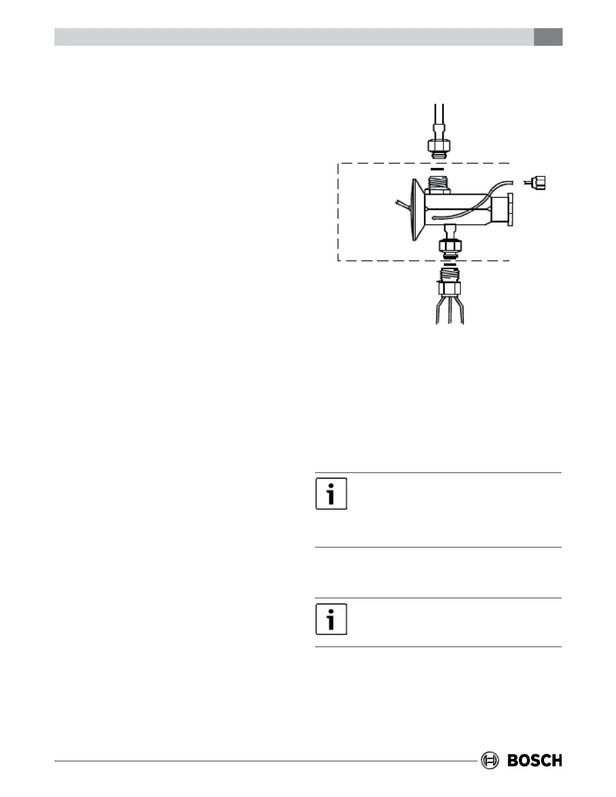
1. After coil pressure has been relieved, turn the
female swivel nut counter-clockwise to remove.
2. Remove the piston from the owrator
distributor tting using a small diameter wire or
paper clip. (ALWAYS REMOVE PISTON FROM
DISTRIBUTOR BODY WHEN TXV IS INSTALLED).
3. Attach the TXV by connecting the female swivel
nut on TXV outlet to the owrator distributor
(aligning Teon seal rst) and torque swivel nut
to 10-30 ft. lbs.
4. Attach liquid line with female swivel nut to male
rotalock tting on TXV inlet (Aligning Teon seal
rst) and torque swivel nut to 10-30 ft. lbs.
Remove the cap on Schrader valve port on coil
manifold. Attach equalizer tubing with 1/4"
female are nut that include depressor to this
male Schrader port. Torque nut to 10-30 ft. lb.
5. Install the TXV bulb to the suction manifold of
coil or the suction line using the two bulb
clamps furnished with kit.
A. Bulb should be installed on a horizontal run
of the manifold if possible. On lines less than
7/8" OD the bulb may be installed on top of
the line. With 7/8" OD and over, the bulb
should be installed in a position at about 4
or 8 o’clock.
B. If bulb installation is made on a vertical run,
the bulb should be located at least 6 inches
from any bend, and on the tubing side
opposite the plane of the bend. On vertical
bulb installations, the bulb should be
positioned with the bulb capillary tube at
the top.
C. The bulb should be insulated using thermal
insulation to protect it from the effect of the
surrounding ambient temperature.
6. After completing installation of TXV (including
equalizer tube), it will be necessary to leak
check the coil and evacuate the coil through the
service access ttings of liquid and suction line
valves.
The unit should be tested after the system has been
completely installed to determine proper operation.
Unit is equipped with heater time delay controls. All
heating elements should turn on within one minute.
Circuitbreakersareequippedwithavisual
“visi-trip”redagindicator.Ifredindicatorshows
thatcircuitbreakerhastripped,thisindicatedthat
aproblemexistsinyoursystemwhichshouldbe
correctedbeforeresettingbreaker.
Heatingsystemshouldnotbeswitchedonuntil
systemislledandalltheairinthehotwatercoil
hasbeenvented.
1. Fill and pressurize the water heater and air
handler.
2. The water heater should be started.