Unit Installation
5.3 Protecting the Unit During Construction
Once the unit is properly positioned on the job site, cover it with
either a shipping carton, vinyl film, or an equivalent protective
covering. Cap opens ends of pipes stored on the job site. This
precaution is especially important in areas where painting,
plastering, or spraying of fireproof material, etc. is not yet
complete. Foreign material that accumulates within the units can
prevent proper start-up and require costly clean-up operations.
Before installing any of the systems components, be sure to
examine each pipe, fitting valves and remove any dirt or foreign
material found in or on these components.
5.4 Take-Apart Construction Option
Units can be ordered with the Take-Apart Construction option,
which allows the unit to be split into two sections to facilitate
installation. If the unit is shipped with this option, follow the
steps below.
1. Unscrew the brackets holding the two sections together
(these can be completely removed from both sections).
2. Separate the sections.
3. Move the split apart sections into the required space.
4. Reconnect the two sections together using the included
copper stubs.
5. Reconnect the condensate drain lines.
6. Reconnect the brackets removed in the first step.
7. Complete the installation as described in the sections that
follow. Charging the unit will be required. Refer to 5.12
Charging the Refrigeration Circuits (for Units with Take-
Apart Construction Only) on page 18.
Be careful not to place the top section flat on a solid floor as
the drain stubs can be damaged and the seal broken.
5.5 Mounting Vertical (VT) Units
All EC units should be vibration isolated according to the design
engineer's specifications.
It is generally not necessary to anchor the unit unless required by
local code.
5.6 Mounting Horizontal (HZ) Units
NOTICE
Plumbing connected to the heat pump must not come in direct
contact with building structure or its components (such as
joists, trusses, walls, etc.).
Some applications require an attic floor installation of the HZ
unit. In those cases, the unit must be set in a full-sized secondary
drain pan on top of a vibration absorbing mesh. The secondary
drain pan prevents possible condensate overflow or water
leakage damage to the ceiling. The secondary drain pan is
normally placed on a plywood base isolated from the ceiling joists
by additional layers of vibration-absorbing mesh. In both cases, a
3/4" drain connected to this secondary pan must be run to an
eave at a location that will be noticeable.
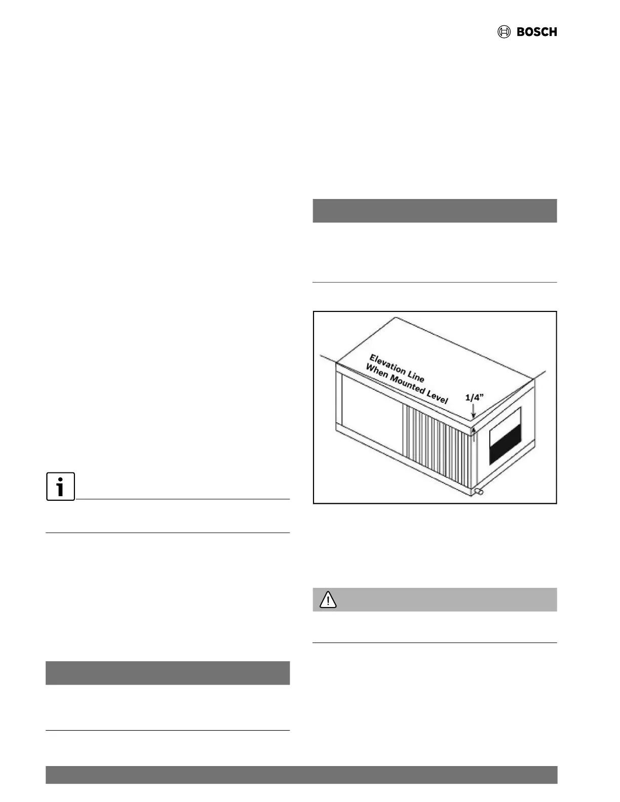
NOTICE
The HZ units condensate drain pans are NOT internally
sloped. HZ units must be installed pitched 1/4" towards the
condensate drain connection in both directions to facilitate
condensate removal. (See Fig. 3.)
Fig. 3 Pitched Unit
If the unit is located in a crawl space, the bottom of the unit must
be at least four inches above grade to prevent flooding of the
electrical parts due to heavy rains.
WARNING
Follow all applicable codes and requirements when hanging
this unit and selecting the threaded rod material, etc.
5.7 Condensate Drain
A drain line must be connected to the heat pump and pitched
away from the unit a minimum of 1/4” per foot to allow the
condensate to flow away from the unit.
12 |
EC Series Heat Pumps — 8733841499 (2024/05)
 Loading...