Factory-Installed Options
14.6.1 MHGRH Sequence of Operation
MHGRH differs from ON/OFF functioning described for HGRH in
that the reheat f
unction is always active. Air is cooled and
dehumidified by the cooling coil to around 55°F DB/54°F WB.
The Reheat Coil raises the air stream temperature to a specified
temperature (adjustable) and reduces relative humidity;
delivering neutral air to the space. A sensor located in the supply
air stream is set at the required leaving dry bulb temperature and
will send a signal to the modulating hot gas reheat valve to direct
the flow of hot gas to maintain that temperature.
14.7 Hot Gas Bypass
The function of hot gas bypass is to prevent icing of the air coil
when the unit is operating at low-load conditions. This situation
could arise if the space experiences widely different heating and
cooling loads or a unit sized for heating that has a much lower
cooling load, for example a conference center.
Without a hot gas bypass circuit the evaporating temperature will
fall and ice
could form on the coil restricting air flow and
aggravating the situation. Eventually the coil could be totally
blocked, resulting in possible refrigerant liquid entering the
compressor and failure of the system.
The hot gas bypass valve, located in the compressor discharge
line, diver
ts hot gas to the inlet of the air coil. The valve is factory
set to open when the evaporating pressure falls to 95 PSI and will
modulate to prevent the pressure falling any lower. This setting is
field adjustable, and this set point may be adjusted as required.
14.7.1 Limit Switch
Units with the hot gas bypass feature include a limit switch on the
suction lin
e, which acts as a safety device. The limit switch shuts
OFF the compressor if it senses the suction pressure is too high.
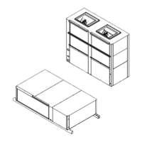
14.8 Economizer
EC series heat pumps can be provided an optional waterside
economizer. The waterside economizer option allows a cooling
demand to be satisfied by circulating cold water through a
Water-to-Air Heat Exchanger (Economizer Coil) mounted to the
return air op
ening of the heat pump instead of energizing the
compressor. If water is below set point but additional cooling is
required, then the aquastat sends a Y2 call that turns ON the
first-stage compressor.
The major components of the Economizer option are the
Economizer Coil, the Motorized Ball Valve (MBV), the aquastat,
and the unit’s
control circuit.
14.8.1 Economizer Sequence of Operation
The Economizer option operates in the following sequence upon
receiving a c
all for cooling by the space sensor:
The “G” terminal energizes the Blower Relay, powering the
Blower Motor.
The “O” terminal energizes the Reversing Valve Coil, setting
the heat pump in the cooling mode and energizing the
Economizer Relay (ER), if the loop water is below the set
point of the aquastat and the switch “AQS” is closed.
The normally-closed contacts of ER open and the normally-
open contacts of ER close.
The MBV will be de-energized in the bypass mode, routing
water directly to the Water-to-Refrigerant Heat Exchanger.
On a rise in space temperature,Y1 closes, which energizes
the MBV Relay if the temperature of the water is below the
aquastat setpoint.
This energize the MBV in the economizer mode, diverting
water first through the Economizer Coil then to the
Water-to-Refrigerant Heat Exchanger in series.
Should the space temperature continue to rise, Y2 is
energized allowing mechanical cooling. If at any time the
water temperature rises above the aquastat set point the
MBV will be energized in the bypass mode and fluid will
bypass the economizer coil.
Note that the Economizer Coil incorporates its own drain pan
to collect condensate from the coil. This pan MUST be
independently trapped and piped into the drain line for the
heat pump.
The EC series Economizer option is designed for free-return
applications. If the heat pump is to be connected to return air
duct work, the Economizer may need to be slightly modified.
The EC series Economizer is designed for cooling only. If
heating economizer operation is desired, consult the factory
for applications and design information.
Refer to the Condensate Drain section on page #12.
| 33
EC Series Heat Pumps — 8733841499 (2024/05)