Maintenance
15.7 Pulley Alignment and Belt Tensioning Procedure
15.7.1 Alignment
Make sure that fan shafts and motor shafts are parallel and level.
The mos
t common causes of misalignment are nonparallel shafts
and improperly located sheaves.
Where shafts are not parallel, belts on one side are drawn tighter
and pul
l more than their share of the load resulting in those belts
wearing out faster and requiring the entire set to be replaced
before they reach their normal rated lifespan.
If the sheave is misaligned, belts enter and leave the grooves at
an angle
, resulting in excessive belt and sheave wear.
Checking Shaft Alignment
Check shaft alignment by measuring the distance between the
shafts a
t three or more locations. If the distances are equal, then
the shafts are parallel.
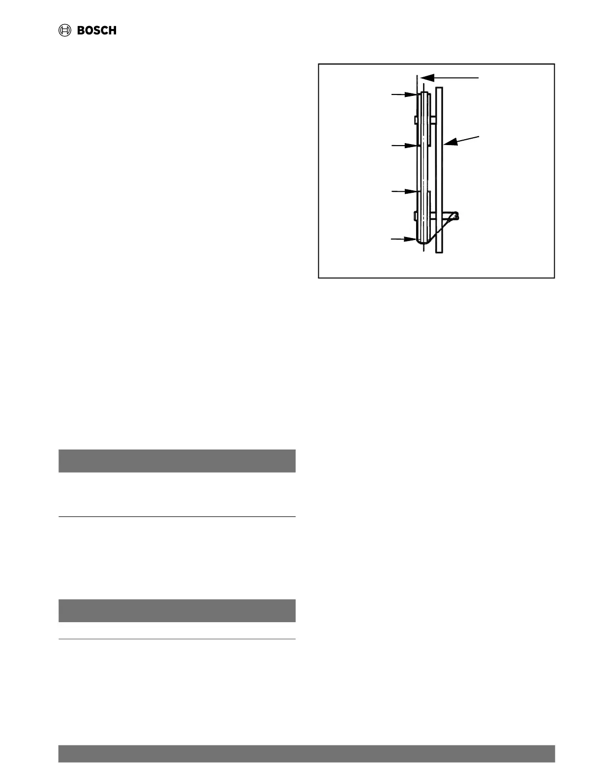
Checking Sheave Alignment
1. Isolate power to the unit. Always follow your Lock-out/Tag-
out procedure.
2. To check the location of the fixed sheaves on the shafts, use
a straightedge or a piece of string. If the sheaves are
properly aligned, the string will touch them at the points
indicated by the four arrows on the left side of Fig. 14.
3. Rotate each sheave a half revolution to determine whether
the sheave is wobbly or the drive shaft is bent.
4. Correct any misalignment.
5. With sheaves aligned, tighten cap screws evenly and
progressively.
NOTICE
There should be a 1/8-in. to 1/4-in. gap between the mating
part hub and the bushing flange. If the gap is closed, the
bushing is probably the wrong size.
6. With taper-lock bushed hubs, ensure the bushing bolts are
tightened evenly to prevent side-to-side pulley wobble.
Check for a wobble by rotating sheaves and rechecking
sheave alignment.
NOTICE
Anytime sheaves have moved, recheck the sheave alignment.
Fig. 14 Sheave Alignment
String
Straight
Edge
Fixed Sheave
15.7.2 Evaporator Fan Performance Adjustment
The motor pulleys used on EC units have a variable pitch. This
means th
at the fan speed can be adjusted depending on the pitch
diameter setting. To change fan speeds from factory settings:
1. Shut off unit power supply. Always follow your Lock-out/
Tag-out procedure.
2. Loosen nuts on the four carriage bolts in the mounting base.
3. Using adjusting bolts and plate, slide the motor and remove
the belt.
4. Loosen movable-pulley flange set screw.
5. Open the variable pitch pulley to decrease fan speed, and
close it to increase fan speed.
6. Increasing the fan speed increases the load on the motor.
7. Replace and tighten the belts.
8. Restore power to the unit.
To align fan and motor pulleys:
1. Loosen fan pulley set screws.
2. Slide fan pulley along fan shaft.
3. Make angular alignment by loosening motor from mounting
plate.
4. Restore power to unit.
15.7.3 Belt Tension Adjustment
Using a gauge, apply 4 lb of force to the center of the belt and
a
djust the
tension until a deflection of 1/64-in. is achieved for
every inch of shaft center distance. (Refer to Fig. 15.)
|
35
EC Series Heat Pumps — 8733841499 (2024/05)