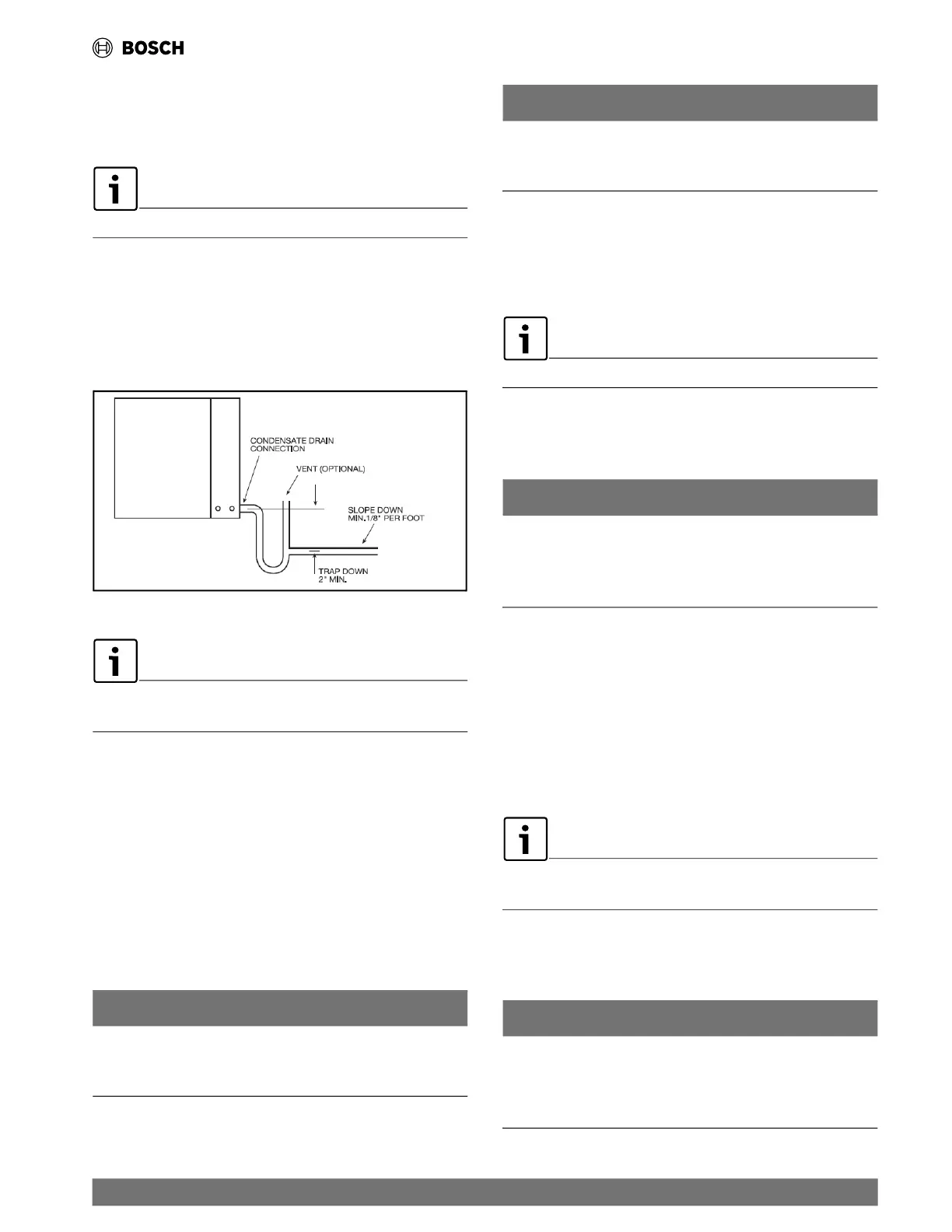
Unit Installation
This connection must be in conformance with local plumbing
codes. A trap must be installed in the condensate line to ensure
free condensate flow.
Units are not internally trapped.
A vertical air vent is sometimes required to avoid air pockets.
The depth of the trap depends on the amount of positive or
negative p
ressure that is on the drain pan while the unit’s fan is
operating. A second trap must NOT be included. (See Fig. 4.)
Fig. 4 Condensate Drain Installation
If the unit is equipped with a float-style condensate overflow
switch, final adjustment must be made in the field.
5.8 Duct System
All EC Series models are provided with a supply air outlet collar
and return air duct flange to facilitate duct connections.
A flexible duct connector is recommended for supply and return
air duct c
onnections on metal duct systems. In order to avoid
heat loss or gain and prevent condensate forming during the
cooling operation, insulate all metal ducting with a minimum of 1"
duct insulation.
NOTICE
Application of the unit to uninsulated duct work is not
recommended as the unit’s performance will be adversely
affected.
NOTICE
The factory-provided air filter must be removed when using a
back-return air grill. The factory filter should be left in place on
a free-return system.
For new or replacement market installations, please refer to
current ASHRAE procedures for duct sizing to ensure proper
unit's operation and air distribution. If the duct system is too
small, larger duct work should be installed. Check for any leaks in
the existing duct work and repair as needed.
DO NOT connect discharge ducts directly to the blower outlet.
5.9 Piping
Supply and return piping must be as large as the unit connections
on the heat pump (larger on long runs).
NOTICE
No unit should be connected to the supply or return piping
until the water system has been completely cleaned and
flushed to remove any dirt, piping chips, or other foreign
material.
Supply and return hoses should be connected together during
this process to ensure the entire system is properly flushed. After
the cleaning and flushing has taken place the unit may be
connected to the water loop and should have all valves wide
open.
In order to avoid possible vibration, use flexible hose between
the unit an
d the rigid system.
Never use flexible hoses of a smaller inside diameter than that
of the water connections on the unit.
Units are equipped with female pipe thread fittings for water
connections.
NOTICE
Piping systems that contains steel pipes or fittings may be
subject to galvanic corrosion. Dielectric fittings should be
used to isolate the steel parts of the system to avoid galvanic
corrosion.
| 13
EC Series Heat Pumps — 8733841499 (2024/05)
 Loading...